LH1529GP Vishay, LH1529GP Datasheet - Page 2
LH1529GP
Manufacturer Part Number
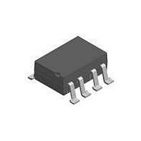
LH1529GP
Description
IC,Telecom Switching Circuit,DIP,8PIN,PLASTIC
Manufacturer
Vishay
Datasheet
1.LH1529GPTR.pdf
(6 pages)
Specifications of LH1529GP
Load Voltage Rating
350 V
Load Current Rating
0.12 A
Contact Form
1 Form A
Output Device
MOSFET
Maximum Operating Temperature
+ 85 C
Minimum Operating Temperature
- 40 C
Package / Case
SMD-8
Output Type
AC, DC
Mounting Style
SMD/SMT
Case Color
Black
Relay Type
Solid State
Lead Free Status / RoHS Status
Lead free / RoHS Compliant
Lead Free Status / RoHS Status
Lead free / RoHS Compliant, Lead free / RoHS Compliant
Available stocks
Company
Part Number
Manufacturer
Quantity
Price
Company:

Part Number:
LH1529GP
Manufacturer:
INFINEON
Quantity:
5 510
Company:
Part Number:
LH1529GP
Manufacturer:
NEC
Quantity:
5 510
Part Number:
LH1529GP
Manufacturer:
VISHAY/威世
Quantity:
20 000


LH1529FP, LH1529FPTR, LH1529GP, LH1529GPTR
Vishay Semiconductors
Notes
•
(1)
Note
•
www.vishay.com
2
THE PRODUCT DESCRIBED HEREIN AND THIS DATASHEET ARE SUBJECT TO SPECIFIC DISCLAIMERS, SET FORTH AT
ABSOLUTE MAXIMUM RATINGS (T
PARAMETER
SSR
INPUT
LED continuous forward current
LED reverse voltage
OUTPUT
DC or peak AC load voltage
Continuous DC load current
SSR
Ambient temperature range
Storage temperature range
Soldering temperature
Isolation test voltage (for 1 s)
Isolation resistance
Power dissipation
OPTOCOUPLER
INPUT
LED continuous forward current
LED reverse voltage
OUTPUT
Collector emitter breakdown voltage
Phototransistor power dissipation
ELECTRICAL CHARACTERISTICS (T
PARAMETER
SSR
INPUT
LED forward current,
switch turn-on
LED forward current,
switch turn-off
LED forward voltage
OUTPUT
On-resistance
Off-resistance
Current limit
Output off-state leakage current
Output capacitance pin 7 to pin 8
OPTOCOUPLER
LED forward current
Saturation voltage
Dark current leakage
Trickle current leakage
DC current transfer ratio
Stresses in excess of the absolute maximum ratings can cause permanent damage to the device. Functional operation of the device is not implied at these or any other conditions in
excess of those given in the operational sections of this document. Exposure to absolute maximum ratings for extended periods of the time can adversely affect reliability.
Refer to reflow profile for soldering conditions for surface mounted devices.
Minimum and maximum values are testing requirements. Typical values are characteristics of the device and are the result of engineering evaluations. Typical values are for information
only and are not part of the testing requirements.
(1)
For technical questions, contact:
I
I
I
I
I
F
I
F
F
F
F
L
I
F
I
I
= 6.0 mA, V
TEST CONDITION
I
= 5 mA, I
= 0 mA, V
I
= 0 mA, V
= 0 mA, V
I
F
F
= 100 mA, t = 10 ms
F
F
F
= 16 mA, I
= 0 mA, V
= 0 mA, V
= 5 μA, V
= 5 mA, t = 5 ms
= 0 mA, V
Telecom Switch - 1 Form A Solid
V
I
I
This datasheet is subject to change without notice.
L
F
F
= ± 300 V
= 10 mA
= 10 mA
amb
L
amb
L
L
L
V
V
= ± 50 mA
C
CE
IO
= ± 100 V
= ± 100 V
= ± 350 V
CE
CE
L
IO
L
= 50 V
= 2 mA
= 25 °C, unless otherwise specified)
= 500 V, T
= 1 V
TEST CONDITION
= 5 V
= 500 V, T
= 5 V
= 0.5 V
= 25 °C, unless otherwise specified)
t = 10 s max.
I
I
I
State Relay
R
R
L
50 μA
10 μA
10 μA
amb
amb
LH1529GP
LH1529FP
optocoupleranswers@vishay.com
= 100 °C
= 25 °C
PART
SYMBOL
CTR
CTR
V
I
I
R
R
I
CEO1
CEO2
I
I
Limit
CEsat
C
C
Fon
Foff
V
V
SYMBOL
OFF
I
I
ON
O
O
F
O
O
F
BV
DC
DC
T
P
P
V
T
T
R
R
V
V
V
amb
I
I
ISO
diss
I
diss
stg
sld
CEO
F
L
F
IO
IO
R
L
R
MIN.
170
100
0.2
0.9
33
1
- 40 to + 125
- 40 to + 85
VALUE
10
10
3000
TYP.
5000
0.07
350
120
260
600
150
210
150
150
1.1
1.2
0.6
1.2
50
50
30
20
55
10
6
6
1
www.vishay.com/doc?91000
12
11
Document Number: 83828
MAX.
Rev. 1.5, 11-Mar-11
250
200
500
1.5
1.5
0.5
25
3
1
1
UNIT
V
mW
mW
mA
mA
mA
°C
°C
°C
RMS
V
V
V
V
UNIT
mA
mA
G
mA
nA
μA
pF
pF
nA
μA
%
%
V
V
V
Related parts for LH1529GP
Image
Part Number
Description
Manufacturer
Datasheet
Request
R


Part Number:
Description:
357-036-542-201 CARDEDGE 36POS DL .156 BLK LOPRO
Manufacturer:
Vishay
Datasheet:
Part Number:
Description:
357-036-542-201 CARDEDGE 36POS DL .156 BLK LOPRO
Manufacturer:
Vishay
Datasheet:
Part Number:
Description:
357-036-542-201 CARDEDGE 36POS DL .156 BLK LOPRO
Manufacturer:
Vishay
Datasheet:
Part Number:
Description:
357-036-542-201 CARDEDGE 36POS DL .156 BLK LOPRO
Manufacturer:
Vishay
Datasheet:
Part Number:
Description:
357-036-542-201 CARDEDGE 36POS DL .156 BLK LOPRO
Manufacturer:
Vishay
Datasheet:
Part Number:
Description:
357-036-542-201 CARDEDGE 36POS DL .156 BLK LOPRO
Manufacturer:
Vishay
Datasheet:
Part Number:
Description:
357-036-542-201 CARDEDGE 36POS DL .156 BLK LOPRO
Manufacturer:
Vishay
Datasheet:
Part Number:
Description:
357-036-542-201 CARDEDGE 36POS DL .156 BLK LOPRO
Manufacturer:
Vishay
Datasheet:
Part Number:
Description:
357-036-542-201 CARDEDGE 36POS DL .156 BLK LOPRO
Manufacturer:
Vishay
Datasheet:
Part Number:
Description:
357-036-542-201 CARDEDGE 36POS DL .156 BLK LOPRO
Manufacturer:
Vishay
Datasheet:
Part Number:
Description:
357-036-542-201 CARDEDGE 36POS DL .156 BLK LOPRO
Manufacturer:
Vishay
Datasheet:
Part Number:
Description:
357-036-542-201 CARDEDGE 36POS DL .156 BLK LOPRO
Manufacturer:
Vishay
Datasheet:
Part Number:
Description:
357-036-542-201 CARDEDGE 36POS DL .156 BLK LOPRO
Manufacturer:
Vishay
Datasheet:
Part Number:
Description:
357-036-542-201 CARDEDGE 36POS DL .156 BLK LOPRO
Manufacturer:
Vishay
Datasheet: