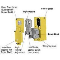
LM5 BANNER ENGINEERING, LM5 Datasheet - Page 16

LM5
Manufacturer Part Number
LM5
Description
Photoelectric Sensor
Manufacturer
BANNER ENGINEERING
Specifications of LM5
Timing Function
On-Delay
Time Range
1.5 Sec. To 15 Sec.
Application
Interconnecting the power block and scanner block
Brand/series
Multi-Beam®
Function
Module, Logic
Includes
Blade & socket connector
Logic Type
ON-Delay
Sensing Mode
Adjustable Field
Technology
Photoelectric
Timing Adjustment
0.5 to 5 Sec.
Lead Free Status / Rohs Status
RoHS Exempt Product
For Use With
Multi-Beam Sensors
Available stocks
Company
Part Number
Manufacturer
Quantity
Price
Part Number:
LM50-22B05
Manufacturer:
MORNSUN/金升阳
Quantity:
20 000
Part Number:
LM50-22B12
Manufacturer:
MORNSUN/金升阳
Quantity:
20 000
Part Number:
LM5000-3MTC
Manufacturer:
NS/国半
Quantity:
20 000
Part Number:
LM5000-3MTCX
Manufacturer:
TI/德州仪器
Quantity:
20 000
Part Number:
LM50003MTC
Manufacturer:
NS/国半
Quantity:
20 000
16
These are power blocks for emitter scanner blocks only (models SBE, SBED, SBEX, SBEV, SBEXD, SBEF, SBEXF). Emitter assemblies do
not require logic modules.
MULTI-BEAM
PBT-1
Input: 10 to 30V dc at less than 60mA (current draw
depends on scanner block used). 10% max. ripple.
PBT48-1
Hookup Diagrams for DC Power Blocks
Input: 44 to 52V dc at less than 60mA (current draw
depends on scanner block used). 10% max. ripple.
When using power blocks with current sinking (NPN)
outputs, simple loads connect between the power block
output (terminal #3) and the positive supply (terminal
#1).
Any number of MULTI-BEAMs may be connected in parallel to one load to create "LIGHT-OR" (light operate
mode) or "DARK-OR" (dark operate mode) multiple sensor logic. In most situations, MULTI-BEAM dc power
blocks cannot wire in series. However, addition of an interposing relay with a normally closed contact or a Banner
logic module will permit "AND" logic with a parallel sensor array.
Hookup to DC Relay or Solenoid
(using sinking output)
Parallel Hookup to a Common Load
Hookup to a Programmable Controller
requiring a current sink
Use power blocks with NPN
outputs to interface to PLCs and
other logic devices requiring a
current sink at the inputs. Con-
nect the output of the power
block (terminal #3) to any input
of the PLC. Also connect the
negative of the MULTI-BEAM
power supply (terminal #2) to
the negative of the PLC power
supply.
To load requiring current sink:
LOAD
+
DC Models
PBT
PBT2
PBT48
LOAD
10 to 30V dc: PBT, PBT2
44 to 52V dc: PBT48
1
3
PBT2
PBT
+10 to 30V dc
3
1
4
2
4
2
30V dc
+10
1
3
to
PBT2
PBT
-
4
2
1
3
PBT2
PBT
4
2
To load requiring current source:
3- & 4-wire DC Power Blocks
+
When using power blocks with current sourcing (PNP)
outputs, simple loads connect between the power block
output (terminal #3) and dc common (terminal #2).
Hookup to DC Relay or Solenoid
(using sourcing output)
+
Connections
3
1
dc com
dc +
PBP
(See Specifications)
1
2
3
4
5
6
7
8
+
4
2
1
PBP
PBP48
N
P
U
S
T
10 to 30V dc
V dc
I
g.
44 to 52V dc: PBP48
P
C
r
o
r
l.
t
10 to 30V dc: PBP
2
3
1
3
1
PBP
4
2
-
Hookup to a Programmable Controller
requiring a current source
Use power blocks with PNP out-
puts to interface to PLCs and
other logic devices requiring a
current source at the inputs. Con-
nect the output of the power block
(terminal #3) to any input of the
PLC. Also connect the negative
of the MULTI-BEAM power
supply (terminal #2) to the nega-
tive of the PLC power supply.
4
2
LOAD
LOAD
-
-
Functional Schematic
Hookup of DC Emitter
MULTI-BEAM emitter-only scanner blocks use dc power
block models PBT-1 or PBT48-1. These power blocks
connect directly across the dc supply, as shown.
A logic zero (0 volts dc) is applied to the gate input
when the MULTI-BEAM output is energized. When
de-energized, a logic one is applied. The logic supply
must be common to the MULTI-BEAM supply nega-
tive.
Hookup to Logic Gate
30V dc
Emitter models:
SBE
SBED
SBEX
SBEV
SBEXD
SBEF
SBEXF
+10
to
(-) dc
* Use pullup resistor
+5V to 30V dc
logic supply
to logic supply
1
3
PBP
Output capacity: 250mA
maximum, each output.
4
2
*
+
+
10 to 30V dc
10 to 30V dc
1
PBT-1
3
1
PBT2
PBT
dc com
4
2
dc+
2
1
2
3
4
5
6
7
8
-
N
P
U
T
S
I
-
g.
P
o
C
l.
r
t
r


