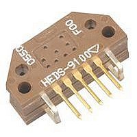
HEDS-9140#G00 Avago Technologies US Inc., HEDS-9140#G00 Datasheet - Page 7

HEDS-9140#G00
Manufacturer Part Number
HEDS-9140#G00
Description
Incremental Encoder
Manufacturer
Avago Technologies US Inc.
Series
HEDS-9140r
Datasheet
1.HEDS-8905.pdf
(13 pages)
Specifications of HEDS-9140#G00
No. Of Channels
2
Rotational Speed Max
30000rpm
Encoder Resolution
360CPR
Supply Voltage Range
4.5VDC To 5.5VDC
Supply Voltage
5V
Output Type
Square Wave Digital Pulse
Pulses Per Revolution
360 CPR
Number Of Channels
3
Mounting Style
PCB
Termination Style
Solder Pin
Product
Optical
Technology
Rotary
Sensor Supply Voltage
4.5VDC To 5.5VDC
Rohs Compliant
Yes
Encoder Output
Square Wave Digital Pulse
Encoder Type
Incremental
Lead Free Status / RoHS Status
Lead free / RoHS Compliant
Available stocks
Company
Part Number
Manufacturer
Quantity
Price
Electrical Interface
To insure reliable encoding performance, the HEDS-9040
and 9140 three channel encoder modules require 2.7
kΩ (±10%) pull-up resistors on output pins 2, 3, and 5
(Channels I, A and B) as shown in Figure 1. These pull-up
resistors should be located as close to the encoder mod-
ule as possible (within 4 feet). Each of the three encoder
module outputs can drive a single TTL load in this con-
fi guration.
Figure 2. HEDS-9X40 Mounting Tolerance.
7
Figure 1. Pull-up Resistors on HEDS-9X40 Encoder Module Outputs.
Mounting Considerations
Figure 2 shows a mounting tolerance requirement for
proper operation of the HEDS-9040 and HEDS-9140. The
Aligning Recess Centers must be located within a toler-
ance circle of 0.005 in. radius from the nominal locations.
This tolerance must be maintained whether the module
is mounted with side A as the mounting plane using
aligning pins (see Figure 5), or mounted with Side B as
the mounting plane using an alignment tool (see Figures
3 and 4).


