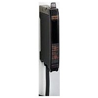
E3XDAB6S Omron, E3XDAB6S Datasheet

E3XDAB6S
Specifications of E3XDAB6S
Related parts for E3XDAB6S
E3XDAB6S Summary of contents
Page 1
... LEDs (4-element type) to ensure super stable, long-term LED performance. Stable performance is always available without the ON/OFF setting of an APC circuit. OMRON’s Innovative Wire-saving Connector Inherited from the E3X-DA-N The amplifier units with connectors supply the power to slave connectors via a master connector. This offers three following advantages. ...
Page 2
... Equipped with an Industry's First ATC Function that Resolves Problems . . . . Advanced ATC Models at Manufacturing Sites OMRON’s unique algorithm is equipped to distinguish dust or dirt and the change of workpieces. Automatic correction of threshold values by sensors in accordance with changes prevents malfunctions and improves the operating rates of machines ...
Page 3
Ordering Information Amplifier Units Amplifier Units with Cables (2 m) [Refer to Dimensions on page 17.] Item Single-function models Standard models Green LED Mark-detecting models Blue LED (multiple color light sources) Infrared LED External-input models Twin-output models Advanced models ATC ...
Page 4
Amplifier Unit Connectors (Order Separately) Note: Protector seals are provided as accessories. Item Appearance Master Connector Slave Connector Combining Amplifier Units and Connectors Amplifier Units and Connectors are sold separately. Refer to the following tables when placing an order. Amplifier ...
Page 5
Ratings and Specifications Amplifier Units Single-function Type models Item Model E3X-DA@SE-S Light source (wavelength) Red LED (635 nm VDC ±10%, ripple (p-p) 10% max. Power supply voltage Power consumption 960 mW max. (current consumption max. ...
Page 6
Type External input mod- els Item Model E3X-DA@RM-S Light source (wavelength) Red LED (635 nm VDC ±10%, ripple (p-p) 10% max. Power supply voltage Power consumption 1,080 mW max. (current consumption max. at power supply ...
Page 7
Type External input models Item Model E3X-DA@RM-S External input set- ting (Select from Func- teaching, power tun- I/O setting tions ing, zero reset, light OFF, or counter re- set.) Operation indicator (orange), Power Display Tuning indicator (or- ange) Select from ...
Page 8
Sensing Distance Through-beam Models Type E32-T11R/E32-T12R/E32-T15XR/ E32-TC200BR(B4R) Flexible E32-T14LR/E32-T15YR/E32-T15ZR (new E32-T21R/E32-T22R/E32-T222R/ standard) E32-T25XR/E32-TC200FR(F4R) E32-T24R/E32-T25YR/E32-T25ZR E32-TC200/E32-T12/E32-T15X/ E32-TC200B(B4) E32-T14L/E32-T15Y/E32-T15Z Standard models Standard E32-TC200A E32-TC200E/E32-T22/E32-T222/ E32-T25X/E32-TC200F(F4) E32-T24/E32-T25Y/E32-T25Z E32-T11/E32-T12B/E32-T15XB Break- E32-T21/E32-T221B/E32-T22B resistant E32-T25XB Fluorine E32-T11U coating E32-T17L E32-TC200 + E39-F1 E32-T11R + E39-F1 E32-T11 ...
Page 9
Type E32-T51 E32-T54 E32-T81R-S Heat- E32-T61-S + E39-F2 resistant E32-T61-S + E39-F1 E32-T84S-S E32-T61-S Environ- E32-T11F ment E32-T12F resistant Chemical E32-T14F models resistant E32-T51F E32-T81F-S E32-T51V E32-T51V + E39-F1V Vacuum E32-T54V resistant E32-T54V + E39-F1V E32-T84SV * The optical fiber ...
Page 10
Type E32-D16 Long distance, E32-D11L high power E32-D21L/E32-D22L E32-D33 Ultracom- pact, ultrafine sleeve E32-D331 E32-CC200R E32-CC200 E32-D32L E32-C31/E32-D32 Special- beam E32-C42 + E39-F3A models Coaxial/small spot E32-D32 + E39-F3A E32-C41 + E39-F3A-5 E32-C31 + E39-F3A-5 E32-C41 + E39-F3B E32-C31 + ...
Page 11
Application-specific Models Type E32-G14 Label detection E32-T14 E32-L25T E32-D36T Liquid-level E32-A01 detection E32-A02 E32-D82F1(F2) E32-L16-N Applica- Glass- E32-A08 tion- substrate specific alignment E32-A07E1(E2) models E32-L66 E32-A09/E32-A09H Glass- substrate Mapping E32-A09H2 E32-A03/E32-A03-1 Wafer E32-T24S mapping E32-A04/E32-A04-1 Soda glass E32-L64 with reflection ...
Page 12
Green, Blue, and Infrared Light Sources Type E32-T11R/E32-T12R/E32-T15XR/ E32-TC200BR(B4R) E32-T14LR/E32-T15YR/E32-T15ZR Through- Standard beam E32-TC200/E32-T12/E32-T15X/ models E32-TC200B(B4) E32-T14L/E32-T15Y/E32-T15Z Special beam E32-T11L/E32-T12L E32-D11R/E32-D12R/E32-D15XR/ E32-DC200BR(B4R) E32-D14LR E32-D15YR/E32-D15ZR Standard E32-DC200/E32-D15X/ E32-DC200B(B4) Reflective E32-D14L models E32-D15Y/E32-D15Z E32-D11L E32-CC200R Special beam E32-CC200 E32-D32L E32-C31/E32-D32 Applica- E32-T14 ...
Page 13
Output Circuit Diagrams NPN Output Operation Model Timing charts mode Incident light No incident light Operation indicator (orange) Light-ON E3X-DA11-S Output transistor E3X-DA6-S Load E3X-DAG11-S (relay) E3X-DAG6-S (Between brown and black leads) E3X-DAB11-S Incident light No incident light E3X-DAB6-S Operation ...
Page 14
PNP Output Opera- Model Timing chart tion mode Incident light No incident light Operation ON indicator OFF (orange) Light-ON ON Output E3X-DA41-S transistor OFF E3X-DA8-S Load Operate E3X-DAG41-S (relay) Reset E3X-DAG8-S (Between blue and black leads) E3X-DAB41-S Incident light E3X-DAB8-S ...
Page 15
Nomenclature Amplifier Units E3X-DA@-S E3X-DA@RM-S E3X-DA@AN-S Sub-Display (Green) Main Display (Red) Threshold, function settings, Incident level, function, etc. etc. Lock lever Locks the fiber. Operation Indicator (orange) ON when output is ON. Mode Selector Power Tuning Indicator OFF when output ...
Page 16
Mounting the End Plate (PFP-M) An End Plate should be used if there is a possibility of the Amplifier Unit moving, e.g., due to vibration Mobile Console is going to be mounted, connect the End Plate in the ...
Page 17
Dimensions Amplifier Units Amplifier Units with Cables E3X-DA11-S E3X-DA41-S E3X-DAG11-S E3X-DAG41 E3X-DAB11-S E3X-DAB41-S Operation indicator E3X-DA11RM-S E3X-DA41RM-S E3X-DA11TW-S E3X-MDA@ only E3X-DA41TW-S 101.45 101.45 E3X-DA11SE-S ch2 E3X-DA41SE-S E3X-DA11AT-S 4 E3X-DA41AT-S 7 E3X-DA11AN-S 4.5 E3X-DA41AN-S 5.65 E3X-MDA11 ch1 ...
Page 18
Amplifier Units with Connectors E3X-DA6-S E3X-DA8-S E3X-DAG6-S E3X-DAG8 E3X-DAB6-S E3X-DAB8-S Operation indicator E3X-DA6RM-S E3X-DA8RM-S E3X-DA6TW-S E3X-MDA@ only E3X-DA8TW-S 101.45 101.45 E3X-DA6SE-S ch2 E3X-DA8SE-S E3X-DA6AT-S 4 E3X-DA8AT-S 7 E3X-MDA6 4.5 E3X-MDA8 5.65 ch1 Four, 2.4 dia. E3X-DA@-S ...
Page 19
Amplifier Unit Connectors Master Connectors E3X-CN11 Edge of amplifier E3X-CN21 * E3X-CN11: 4 dia. 4 dia. cable / 3 conductors 3 conductors / Standard length (Conductor cross section: 0.2 mm E3X-CN21: 4 dia. 4 dia. cable / 4 ...
Page 20
Mobile Console E3X-MC11-SV2 AC adapter jack Menu indicators 22 Sensor operation indicator Channel buttons UP key LEFT key DOWN key ENT key Battery indicators Mobile Console Communications jack Optical communications connection indicator 52.8 Channel indicator Main display 24.3 30.3 Sub-display ...
Page 21
... Please read and understand this catalog before purchasing the products. Please consult your OMRON representative if you have any questions or comments. WARRANTY OMRON's exclusive warranty is that the products are free from defects in materials and workmanship for a period of one year (or other period if specified) from date of sale by OMRON. OMRON MAKES NO WARRANTY OR REPRESENTATION, EXPRESS OR IMPLIED, REGARDING NON-INFRINGEMENT, MERCHANTABILITY, OR FITNESS FOR PARTICULAR PURPOSE OF THE PRODUCTS ...


