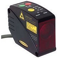
LT3NILVQ BANNER ENGINEERING, LT3NILVQ Datasheet - Page 3

LT3NILVQ
Manufacturer Part Number
LT3NILVQ
Description
Proximity Sensor
Manufacturer
BANNER ENGINEERING
Type
Analog And Discrete Outputr
Datasheet
1.LT3NILVQ.pdf
(12 pages)
Specifications of LT3NILVQ
Sensor Output
NPN
Contact Current Max
20mA
Switch Terminals
Quick Connect
Peak Reflow Compatible (260 C)
No
Sensor Housing
Rectangular
Sensor Input
Laser
Output Type
Transistor
Sensing Range Max
50m
Leaded Process Compatible
No
Fiber Optic Sensor Type
Analog And Discrete Output
Figure 3. Analog output as a function of
10
20
0
4
NOTE: The linear analog output tracks slightly past
each window limit (from 3.8 to 20.5 mA)
Window
target position
Window
Banner Engineering Corp.
Near
Near
Voltage-Sourcing Models
Current-Sourcing Models
www.bannerengineering.com • Tel: 763.544.3164
Target Position
Target Position
Positive
Positive
Slope
Slope
L-GAGE
Window
Window
Far
Far
•
Minneapolis, MN U.S.A.
®
LT3 Time-of-Flight Sensor –
Window Limits
Window limits may be taught to the sensor in several ways, either using the push buttons
on the top of the sensor or via a remote switch.
Remote Programming
To program the sensor remotely or to disable the keypad, the Remote Programming
function may be used. Disabling the keypad prevents accidental or unauthorized
adjustment of the programming settings. Connect the yellow wire of the sensor to
+5 to 24V dc, with a remote programming switch connected between them.
NOTE: The impedance of the remote teach input is 55 kΩ.
Programming is accomplished by following the sequence of input pulses. The duration
of each pulse (corresponding to a push button “click”), and the period between multiple
pulses, are defined as “T”: 0.04 seconds ≤ T ≤ 0.8 seconds.
Analog Output Slope
The L-GAGE LT3 Sensor may be programmed for either a positive or a negative output
slope, based on which condition is taught first (see Figure 3). If the near limit is taught
first, the slope will be positive; if the far limit is taught first, the slope will be negative.
Banner’s unique scalable analog output (patent pending) automatically distributes the
output signal over the width of the programmed sensing window.
In the event of analog signal loss for longer than 2 seconds, the analog output goes to
0V dc or 3.6 mA, which may be used to trigger an alarm.
Teaching Analog Limits Using the Auto-Zero Feature (Analog Output)
For some analog applications, a sensing distance set point centered within a sensing
window may be required. The TEACH procedure is simple: teaching the same limit
twice causes the sensor to program a window centered on the position taught. This
window is 10 m wide (taught position ± 5 m).
Teaching Discrete Limits for Background Suppresson
For some applications, ignoring objects beyond a certain distance may be required. To
suppress the background, place a target object at the selected distance, and teach the
position twice. The sensor’s discrete output will activate when an object is detected
between the sensor’s minimum sensing distance and the taught position.
NOTE: The sensor allows for some forgiveness in this procedure. If the two limits are
not exactly the same (but less than 20 mm apart), the sensor will put the set
point at the “average” of the two limits.
Retro, Analog/Discrete
P/N 68504 rev. C
3


