SHT71 SENSIRION, SHT71 Datasheet - Page 7
SHT71
Manufacturer Part Number
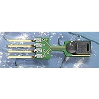
SHT71
Description
Humidity Sensor
Manufacturer
SENSIRION
Datasheet
1.SHT71.pdf
(11 pages)
Specifications of SHT71
Sensing Accuracy
3%
Sensor Output
Digital
Sensor Terminals
Through Hole
Peak Reflow Compatible (260 C)
Yes
Terminal Type
PCB Surface Mount
Humidity Range
0 To 100% RH
Response Time
8s
Humidity Accuracy ±
3%
Rohs Compliant
Yes
Leaded Process Compatible
Yes
Package / Case
4-SIP
Lead Free Status / RoHS Status
Lead free / RoHS Compliant


Datasheet SHT7x
Figure 12: Example RH measurement sequence for value “0000’0100“0011’0001” = 1073 = 35.50%RH (without temperature
compensation). DATA valid times are given and referenced in boxes on DATA line. Bold DATA lines are controlled by sensor while plain
lines are controlled by the micro-controller.
Bit Type Description
Table 5: Status Register Bits
Measurement resolution: The default measurement
resolution of 14bit (temperature) and 12bit (humidity) can
be reduced to 12 and 8bit. This is especially useful in high
speed or extreme low power applications.
End of Battery function detects and notifies VDD voltages
below 2.47 V. Accuracy is 0.05 V.
Heater: An on chip heating element can be addressed by
writing a command into status register. The heater may
increase the temperature of the sensor by 5 – 10°C
beyond ambient temperature. The heater draws roughly
8mA @ 5V supply voltage.
12
www.sensirion.com
7
6 R
5
4
3
2 R/W Heater
1 R/W no reload from OTP
0 R/W
SCK
DATA
SCK
DATA
SCK
DATA
Corresponds to 9 – 18°F
reserved
End of Battery (low voltage
detection)
‘0’ for VDD > 2.47
‘1’ for VDD < 2.47
reserved
reserved
For Testing only, do not use
’1’ = 8bit RH / 12bit Temp.
resolution
’0’ = 12bit RH / 14bit Temp.
resolution
15
Transmission Start
7
15
MSb
7
14
14
6
Idle Bits
6
13
13
5
5
CRC-8 Checksum
12
12
4
4
11
Default
MSb
11
X
0
0
0
0
0 off
0 reload
0
3
3
No default value,
bit is only updated
after a
measurement
12bit RH
14bit Temp.
10
10
2
A2
Address = ‘000’
A2
2
9
9
1
A1
A1
Version 4.3 – May 2010
1
8
8
LSb
0
A0
A0
0
12
C4
C4
ACK
ACK
ACK
12bit Humidity Data
ACK
Command = ‘00101’
C3
C3
For example the heater can be helpful for functionality
analysis: Humidity and temperature readings before and
after applying the heater are compared. Temperature shall
increase while relative humidity decreases at the same
time. Dew point shall remain the same.
Please note: The temperature reading will display the
temperature of the heated sensor element and not
ambient temperature. Furthermore, the sensor is not
qualified for continuous application of the heater.
OTP reload: With this operation the calibration data is
uploaded to the register before each measurement. This
may be deactivated for reducing measurement time by
about 10ms.
4 Conversion of Signal Output
4.1
For compensating non-linearity of the humidity sensor –
see Figure 13 – and for obtaining the full accuracy of the
sensor it is recommended to convert the humidity readout
(SO
Table 6:
Table 6: Optimized V4 humidity conversion coefficients
RH
7
7
RH
linear
C2
Sleep (wait for next
C2
SO
12 bit
8 bit
6
) with the following formula with coefficients given in
measurement)
Relative Humidity
6
RH
C1
C1
c
5
5
1
C0
C0
c
4
2
4
-2.0468
-2.0468
ACK
ACK
SO
c
3
1
3
RH
Measurement (80ms for 12bit)
Transmission Start
2
Sensor pulls DATA line low after
completion of measurement
2
c
3
1
0.0367
0.5872
1
SO
c
2
LSb
0
RH
0
2
(%RH)
Skip ACK to end trans-
mission (if no CRC is used)
-1.5955E-6
-4.0845E-4
ACK
ACK
c
3
7/11
Related parts for SHT71
Image
Part Number
Description
Manufacturer
Datasheet
Request
R


Part Number:
Description:
MODULE SENSOR TEMP+HUMIDITY
Manufacturer:
Parallax Inc
Datasheet:

Part Number:
Description:
Humidity Sensor Filter Cap
Manufacturer:
SENSIRION
Datasheet:

Part Number:
Description:
Sensor Evaluation Kit
Manufacturer:
SENSIRION
Datasheet:

Part Number:
Description:
Sensor Evaluation Kit
Manufacturer:
SENSIRION
Datasheet:
Part Number:
Description:
Sensor Evaluation Kit
Manufacturer:
SENSIRION
Datasheet:
Part Number:
Description:
Sensor Evaluation Kit
Manufacturer:
SENSIRION
Datasheet:


Part Number:
Description:
SENSOR, MASS FLOW
Manufacturer:
SENSIRION
Datasheet:

Part Number:
Description:
Humidity Sensor
Manufacturer:
SENSIRION
Datasheet: