Q60BB6AFV1000Q BANNER ENGINEERING, Q60BB6AFV1000Q Datasheet - Page 3
Q60BB6AFV1000Q
Manufacturer Part Number
Q60BB6AFV1000Q
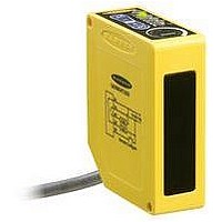
Description
Photoelectric Sensor
Manufacturer
BANNER ENGINEERING
Type
Adjustable Fieldr
Specifications of Q60BB6AFV1000Q
Output Current
150mA
Sensor Output
NPN/PNP
Supply Voltage Range Dc
10V To 30V
Sensor Housing
Rectangular
Sensing Range Min
65mm
Sensor Input
Optical
Body Material
ABS Polycarbonate
Brand/series
Q60AFV
Current, Switching
150 mA
Function
Proximity
Ip Rating
IP67
Output
NPN/PNP
Primary Type
Photoelectric
Range, Measurement
1000 mm
Sensing Mode
Adjustable Field
Technology
Photoelectric
Termination
5-Wire Connector
Voltage, Supply
30 VDC
Accessories Available
Cordsets and Brackets
Contact Current Max
50mA
Sensing Range Max
1000mm
Lead Free Status / Rohs Status
RoHS Exempt Product


Figure 4. Set cutoff distance approximately
Figure 5. Setting the cutoff distance
Figure 6. Reflective background – problem
Figure 7. Reflective background – solution
Banner Engineering Corp.
DO
www.bannerengineering.com • Tel: 763.544.3164
midway between the farthest
target and the closest background
RANGE
E
R1 = Near Detector
R2 = Far Detector
DELAY
E
R1 = Near Detector
R2 = Far Detector
R1
R2
ON
= Emitter
E
R2
R1
E
= Emitter
R2
R1
E
Core of
Emitted
Beam
Core of
Emitted
Beam
Sensing
Field
Sensing
Field
Target
Strong
Direct
Reflection
to R1
Set Cutoff Midway
Between
Farthest Target Object
Closest Background
•
Distance
Minneapolis, MN U.S.A.
Cutoff
Cutoff
Distance
Strong
Direct
Reflection
Away From
Sensor
Q60V Series Adjustable-Field Sensors –
Cutoff
Distance
Background
Reflective
Background
Reflective
Background
Setting the Cutoff Distance
The cutoff distance for Q60AFV sensors may be adjusted between 200 mm and
1000 mm (8" to 40").
To maximize contrast, position the lightest possible background to be used, at the
closest position it will come to the sensor during use (Figure 4). Using a small
screwdriver in the adjustment screw, adjust the cutoff distance until the threshold is
reached and the green Light Sensed indicator changes state. (If the indicator never
comes ON, the background is beyond the maximum sensing cutoff and will be
ignored.) Note the position of the rotating cutoff position indicator at this position.
Then repeat the procedure, using the darkest target, placed in its most distant
position for sensing. Adjust the cutoff so that the indicator is midway between the two
positions (Figure 5).
NOTE: Setting the cutoff distance adjustment screw to its maximum clockwise
Sensing Reliability
For highest sensitivity, the sensor-to-object distance should be such that the object
will be sensed at or near the point of maximum excess gain. The excess gain curves
on page 1 show excess gain vs. sensing distance for 200 mm and 1 m cutoffs.
Maximum excess gain for a 200 mm cutoff occurs at a lens-to-object distance of
about 150 mm, and for a 1 m cutoff, at about 400 mm. The background must be
placed beyond the cutoff distance. Following these two guidelines makes it possible
to detect objects of low reflectivity, even against close-in reflective backgrounds.
Background Reflectivity and Placement
Avoid mirror-like backgrounds that produce specular reflections. False sensor re-
sponse will occur if a background surface reflects the sensor’s light more strongly to
the near detector (R1) than to the far detector (R2). The result is a false ON condition
(Figure 6). Use of a diffusely-reflective (matte) background will cure this problem.
Other possible solutions are to angle either the sensor or the background (in any
plane) so that the background does not reflect back to the sensor (see Figure 7).
An object beyond the cutoff distance, either moving or stationary (and when posi-
tioned as shown in Figure 8), can cause unwanted triggering of the sensor because it
reflects more light to the near detector than to the far detector. The problem is easily
remedied by rotating the sensor 90° (Figure 9) to align the sensing axis horizontally.
The object then reflects the R1 and R2 fields equally, resulting in no false triggering.
Figure 8. Object beyond cutoff distance —
position places the receiver lens directly in front of the receiver elements and
results in the Q60 performing as a long-range diffuse sensor.
problem
R2
R1
E
Sensing
Field
Distance
Cutoff
Sensor Setup
Figure 9. Object beyond cutoff distance —
E, R1, R2
solution
Visible Red Emitter
Sensing
Field
page
3
Related parts for Q60BB6AFV1000Q
Image
Part Number
Description
Manufacturer
Datasheet
Request
R

Part Number:
Description:
Photoelectric Sensor
Manufacturer:
BANNER ENGINEERING
Datasheet:

Part Number:
Description:
Photoelectric Sensor
Manufacturer:
BANNER ENGINEERING
Datasheet:

Part Number:
Description:
LEDIR70XD4-XM-81039 MAX INTENS STROBE ONLY NO BANNER MARKS
Manufacturer:
BANNER ENGINEERING
Part Number:
Description:
M18SP6DL-72225 LABELED MOELLER NO BANNER MARKINGS BULK PACK
Manufacturer:
BANNER ENGINEERING
Part Number:
Description:
M18SP6DLQ-72226 LABLED MOELLER NO BANNER MARKINGS BULK PACK
Manufacturer:
BANNER ENGINEERING
Part Number:
Description:
M18SP6L-72223 LABELED MOELLER NO BANNER MARKINGS BULK PACK
Manufacturer:
BANNER ENGINEERING
Part Number:
Description:
M18SP6LQ-72224 LABELED MOELLER NO BANNER MARKINGS BULK PACK
Manufacturer:
BANNER ENGINEERING
Part Number:
Description:
P4D1-77908 P4 DRIVER GENERIC NO BANNER MARKINGS RESALE TO CUSTOMER
Manufacturer:
BANNER ENGINEERING
Part Number:
Description:
Photoelectric Sensor
Manufacturer:
BANNER ENGINEERING
Datasheet:

Part Number:
Description:
Programmable Indicator Light
Manufacturer:
BANNER ENGINEERING
Datasheet:
Part Number:
Description:
INDICATOR LED PANEL 50MM GRN/RED/YEL 30V
Manufacturer:
BANNER ENGINEERING
Datasheet:
Part Number:
Description:
Programmable Indicator Light
Manufacturer:
BANNER ENGINEERING
Datasheet: