Q85VR3LP-T9 BANNER ENGINEERING, Q85VR3LP-T9 Datasheet - Page 5
Q85VR3LP-T9
Manufacturer Part Number
Q85VR3LP-T9
Description
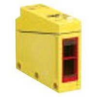
Photoelectric Sensor
Manufacturer
BANNER ENGINEERING
Type
Polarized Retroreflectiver
Datasheet
1.Q85VR3LP-T9.pdf
(8 pages)
Specifications of Q85VR3LP-T9
Sensing Range
0m To 4.6m
Output Current
3A
Sensor Output
SPDT-Relay
Sensing Range Max
4.6m
Supply Voltage Dc, Max
240V
Supply Voltage Ac, Max
240V
Fiber Optic Applications
Conveyor Control
Fiber Optic Sensor Type
Polarized Retroreflective


Supply Voltage and Current
Supply Protection Circuitry
Output Configuration
Output Rating
Output Protection Circuitry
Output Response Time and
Repeatability
Adjustments
Indicators
Construction
Environmental Rating
Operating Conditions
Vibration and
Mechanical Shock
Certifications
Banner Engineering Corp. • Minneapolis, MN U.S.A.
www.bannerengineering.com • Tel: 763.544.3164
*NOTE: Connection of dc power is without regard to polarity
Q853E Emitter
24 to 240V ac, 50/60 Hz or 12 to 240V dc (2 watts maximum)
Protected against transient voltages. DC hookup is without regard to polarity.
Q85BW13.. models: optically isolated SPST solid-state switch, ON/OFF output
Q85BW13..-T9 models: optically isolated SPST solid-state switch, selectable timer
250V ac, 250V dc, 300 mA
Output saturation voltage: 3V at 300 mA, 2V at 15 mA
Off-state leakage current: <50 microamps
Inrush current: 1 amp for 20 milliseconds, non-repetitive
Protected against false pulse on power up
Response time and repeatability are independent of signal strength:
Single-turn Sensitivity control potentiometer, accessible beneath the ABS wiring chamber cover. Timing logic (for “T9”
models) is configured via DIP switch. Pulse length and delay are set by a single-turn potentiometer (under the wiring
chamber cover). The adjustable time range for both functions is 0.1 to 5 seconds; both functions are automatically set
to the same value. All models have a light/dark operate switch under the wiring chamber cover.
Exclusive Alignment Indicating Device system (AID™) lights a red LED indicator whenever the sensor sees its own
modulated light, and pulses at a rate proportional to the strength of the light signal. Yellow indicator lights whenever
the sensor’s output is conducting.
Yellow ABS housing, acrylic lenses, and steel-plated hardware.
Maximum wire size (for connection to wiring terminals) is #14 AWG.
Meets NEMA standards 1, 2, 3, 3S, 4, 4X, 6, 6P, 12, and 13; IEC IP67
Temperature:
Max. Relative Humidity: 90% at 50°C (non-condensing)
Meets Mil. Std. 202F requirements.
Method 201A (Vibration: frequency 10 to 55 Hz max., douple-amplitude 0.06", max. acceleration 10G)
Method 213B conditions H & I (Shock: 75G with unit operating; 100G for non-operation)
1
2
3
4
5
Q85BW13R
Q85BW13LP
Q85BW13D
Q85BW13DL
*ON/OFF operation (no timing in use)
Model
Q85BW13 Model Specifications
Response Time Repeatability
6 ms ON/
3 ms OFF
4 ms ON/OFF
4 ms ON/OFF
4 ms ON/OFF
NRTL/C
Q85BW13 Model Hookups
24-240V ac
or 12-240V dc*
–25° to +55°C (–13° to +131°F)
750 µs
1 ms
1 ms
1 ms
*NOTE: Connection of dc power is without regard to polarity
Other Q85BW13 Models
Q85BW13R-T9
Q85BW13LP-T9
Q85BW13D-T9
Q85BW13DL-T9
Model*
1
2
3
4
5
Isolated
solid-state
SPST switch
Response Time Repeatability
12 ms ON/
9 ms OFF
10 ms ON/OFF
10 ms ON/OFF
10 ms ON/OFF
24-240V ac
or 12-240V dc*
Q85 Sensors
1 ms
1 ms
1 ms
1 ms
P/N 137791
5
Related parts for Q85VR3LP-T9
Image
Part Number
Description
Manufacturer
Datasheet
Request
R

Part Number:
Description:
Photoelectric Sensor
Manufacturer:
BANNER ENGINEERING
Datasheet:

Part Number:
Description:
Photoelectric Sensor
Manufacturer:
BANNER ENGINEERING
Datasheet:

Part Number:
Description:
LEDIR70XD4-XM-81039 MAX INTENS STROBE ONLY NO BANNER MARKS
Manufacturer:
BANNER ENGINEERING
Part Number:
Description:
M18SP6DL-72225 LABELED MOELLER NO BANNER MARKINGS BULK PACK
Manufacturer:
BANNER ENGINEERING
Part Number:
Description:
M18SP6DLQ-72226 LABLED MOELLER NO BANNER MARKINGS BULK PACK
Manufacturer:
BANNER ENGINEERING
Part Number:
Description:
M18SP6L-72223 LABELED MOELLER NO BANNER MARKINGS BULK PACK
Manufacturer:
BANNER ENGINEERING
Part Number:
Description:
M18SP6LQ-72224 LABELED MOELLER NO BANNER MARKINGS BULK PACK
Manufacturer:
BANNER ENGINEERING
Part Number:
Description:
P4D1-77908 P4 DRIVER GENERIC NO BANNER MARKINGS RESALE TO CUSTOMER
Manufacturer:
BANNER ENGINEERING
Part Number:
Description:
Photoelectric Sensor
Manufacturer:
BANNER ENGINEERING
Datasheet:

Part Number:
Description:
Programmable Indicator Light
Manufacturer:
BANNER ENGINEERING
Datasheet:
Part Number:
Description:
INDICATOR LED PANEL 50MM GRN/RED/YEL 30V
Manufacturer:
BANNER ENGINEERING
Datasheet:
Part Number:
Description:
Programmable Indicator Light
Manufacturer:
BANNER ENGINEERING
Datasheet: