SMU31E BANNER ENGINEERING, SMU31E Datasheet - Page 10
SMU31E
Manufacturer Part Number
SMU31E
Description
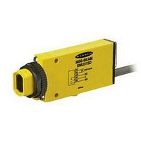
Photoelectric Sensor
Manufacturer
BANNER ENGINEERING
Type
Emitterr
Specifications of SMU31E
Output Current
3A
Supply Voltage Range Dc
24V To 240V
Sensor Input
Optical
Output Type
Relay
Sensing Range Max
3m
Contact Current Max
3A
Switch Terminals
Cable
Sensing Mode
Opposed
Brand/series
Mini-Beam®
Current, Switching
3 A
Ip Rating
IP67
Mounting Type
Threaded
Output
Relay
Primary Type
Photoelectric
Range, Measurement
3 m
Technology
Photoelectric
Termination
Cable
Voltage, Supply
240 VAC/VDC
Voltage, Switching
250/30 VAC/VDC
Lead Free Status / Rohs Status
RoHS Exempt Product


MINI-BEAM Universal Voltage Series
page
GROUP I Emitter/ Receiver
Pairs (see RANGE columns
at right):
GROUP II Emitter/ Receiver
Pairs (see RANGE columns
at right):
Example:
The MINI-BEAM SMU1E/
SMU31R sensor pair is in
Group I. With an AP31-040
circular aperture on the
receiver only, range is
940 mm (37"). With
AP31-040 apertures on
both emitter and receiver,
range is 330 mm (13").
Group I range with
AP31-040 apertures and
UC-300EL upper covers on
both units is 483 mm (19");
range with receiver aperture
only is 2.0 m (80").
AP31-020
AP31-040
AP31-100
AP31-020H
AP31-040H
AP31-100H
AP31-200H
AP31-020V
AP31-040V
AP31-100V
AP31-200V
AP31-DVHX2
SMU31E/SMU31R
SMU31EL/SMU31RL
Opposed-mode MINI-BEAM sensors may be fitted with apertures which narrow or shape the effective beam of the sensor to more closely match the size
or profile of the object to be sensed, for example, the use of “line” (or “slit”) apertures for sensing wire or thread. Each model contains 20 apertures.
10
Definitions
Model
Range of MINI-BEAM Opposed-Mode Sensor Pairs when Used with Apertures
Aperture(s)
AP31-020
AP31-040
AP31-100
AP31-020H
AP31-040H
AP31-100H
AP31-200H
AP31-020V
AP31-040V
AP31-100V
AP31-200V
0.5 mm (0.02") diameter, circular
1.0 mm (0.04") diameter, circular
2.5 mm (0.10") diameter, circular
0.5 x 6.4 mm (0.02" x 0.25"), horizontal slotted
1.0 x 6.4 mm (0.04" x 0.25"), horizontal slotted
2.5 x 6.4 mm (0.10" x 0.25"), horizontal slotted
5.1 x 6.4 mm (0.20" x 0.25"), horizontal slotted
0.5 x 12.7 mm (0.02" x 0.50"), vertical slotted
1.0 x 12.7 mm (0.04" x 0.50"), vertical slotted
2.5 x 12.7 mm (0.10" x 0.50"), vertical slotted
5.1 x 12.7 mm (0.20" x 0.50"), vertical slotted
Kit containing two of each aperture
Used
Sensors
Group I
330 mm
406 mm
914 mm
457 mm
Emitter & Receiver
89 mm
(110")
(110")
1.5 m
2.3 m
2.8 m
1.0 m
2.3 m
2.8 m
(3.5")
(13 ")
(60")
(16")
(36")
(90")
(18")
(40")
(90")
Both Apertured
Standard Group I and II Sensor Pairs
Group II
Sensors
102 mm
457 mm
10.4 m
21.3 m
10.7 m
22.9 m
3.0 m
1.8 m
4.0 m
1.7 m
5.5 m
(4.0")
(18")
(10')
(70")
(13')
(34')
(70')
(65")
(18')
(35')
(75')
Apertures
RANGE
Sensors
Group I
457 mm
940 mm
965 mm
(100")
(114")
(120")
(114")
(120")
2.5 m
1.8 m
2.9 m
3.0 m
1.0 m
1.8 m
2.9 m
3.0 m
(18")
(37")
(38")
(72")
(40")
(70")
Receiver Only
Description
Apertured
Group II
Sensors
Banner Engineering Corp. • Minneapolis, U.S.A.
Website: http://www.baneng.com • Tel: 888.373.6767
12.5 m
20.7 m
24.4 m
15.8 m
22.9 m
25.9 m
(10.5')
1.5 m
3.2 m
8.2 m
9.1 m
8.2 m
(60")
(27')
(30')
(41')
(68')
(80')
(27')
(52')
(75')
(85')
UC-300EL Upper Covers Substituted
Emitter & Receiver
Both Apertured
Group I Sensor Pairs with
127 mm
483 mm
864 mm
8.5 mm
2.1 m
1.8 m
5.2 m
8.2 m
1.0 m
2.1 m
6.1 m
(5.0")
(19")
(84")
(34")
(72")
(17')
(27')
(40")
(84")
(20')
(28')
RANGE
Receiver Only
Apertured
914 mm
11.0 m
11.0 m
2.0 m
5.8 m
3.4 m
5.2 m
8.5 m
3.4 m
5.5 m
8.5 m
(36")
(80")
(19')
(11')
(17')
(28')
(36')
(11')
(18')
(28')
(36')
Related parts for SMU31E
Image
Part Number
Description
Manufacturer
Datasheet
Request
R

Part Number:
Description:
Photoelectric Sensor
Manufacturer:
BANNER ENGINEERING
Datasheet:

Part Number:
Description:
Photoelectric Sensor
Manufacturer:
BANNER ENGINEERING
Datasheet:

Part Number:
Description:
LEDIR70XD4-XM-81039 MAX INTENS STROBE ONLY NO BANNER MARKS
Manufacturer:
BANNER ENGINEERING
Part Number:
Description:
M18SP6DL-72225 LABELED MOELLER NO BANNER MARKINGS BULK PACK
Manufacturer:
BANNER ENGINEERING
Part Number:
Description:
M18SP6DLQ-72226 LABLED MOELLER NO BANNER MARKINGS BULK PACK
Manufacturer:
BANNER ENGINEERING
Part Number:
Description:
M18SP6L-72223 LABELED MOELLER NO BANNER MARKINGS BULK PACK
Manufacturer:
BANNER ENGINEERING
Part Number:
Description:
M18SP6LQ-72224 LABELED MOELLER NO BANNER MARKINGS BULK PACK
Manufacturer:
BANNER ENGINEERING
Part Number:
Description:
P4D1-77908 P4 DRIVER GENERIC NO BANNER MARKINGS RESALE TO CUSTOMER
Manufacturer:
BANNER ENGINEERING
Part Number:
Description:
Photoelectric Sensor
Manufacturer:
BANNER ENGINEERING
Datasheet:

Part Number:
Description:
Programmable Indicator Light
Manufacturer:
BANNER ENGINEERING
Datasheet:
Part Number:
Description:
INDICATOR LED PANEL 50MM GRN/RED/YEL 30V
Manufacturer:
BANNER ENGINEERING
Datasheet:
Part Number:
Description:
Programmable Indicator Light
Manufacturer:
BANNER ENGINEERING
Datasheet: