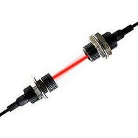
CX-21 PANASONIC EW, CX-21 Datasheet - Page 9

CX-21
Manufacturer Part Number
CX-21
Description
PHOLOELECTRIC SENSOR
Manufacturer
PANASONIC EW
Datasheet
1.CX-21.pdf
(14 pages)
Specifications of CX-21
Output Current
100mA
Sensor Output
NPN Open Collector
Supply Voltage Range Dc
12V To 24V
Lead Free Status / RoHS Status
Lead free / RoHS Compliant
Available stocks
Company
Part Number
Manufacturer
Quantity
Price
Company:
Part Number:
CX-21
Manufacturer:
Coilcraft
Quantity:
8 500
CX-20
PRECAUTIONS FOR PROPER USE
Retroreflective type sensor with polarizing filters
• If a shiny object is covered or wrapped with a transparent
Self-diagnosis function (Self-diagnosis output type only)
• The sensor diagnoses the incident light intensity, and if it
1 The self-diagnosis output transistor stays in the ‘OFF’ state during stable
2 When the sensing output changes, if the incident light intensity does not
3 In case of insufficient beam interruption, there will be a time lag before
DIMENSIONS (Unit: mm)
Notes: 1) Not incorporated on the emitter of the thru-beam type sensor.
Notes:
Sensing output
(operation indicator )
(in the Light-ON mode)
168
film, such as those described below, the retroreflective
type sensor with polarizing filters may not be able to
detect it.
In that case, follow the steps given below.
Steps
is reduced due to dirt or dust, or beam misalignment, an
output is generated.
Example of sensing objects
Self-diagnosis output
Center of
sensing
sensing.
reach the stable light received level or the stable dark level, the self-
diagnosis output becomes ON.
Further, the self-diagnosis output changes state when the sensing output
changes from Light to Dark state. (It is not affected by the operation
mode switch.)
the self-diagnosis output turns ON.
• Can wrapped by clear film
• Aluminum sheet covered by plastic film
• Gold or silver color (glossy) label or wrapping paper
• Tilt the sensor with respect to the sensing object while fitting.
• Reduce the sensitivity.
• Increase the distance between the sensor and the sensing
Sensing condition
object.
Stability indicator
2) It is the power indicator (red) on the emitter of the thru-beam type
CX-2
sensor.
12
Stability indicator (Green) (Note 1)
Operation indicator (Red) (Note 2)
2-M3
thru-hole threads
1
Insufficient
beam intensity
Sensor
1.7
31
0.5
15.5
"3.7 cable 2m long
2
25
3
Insufficient
beam interruption
20
1
3
Operation mode switch (Note 1)
Sensitivity adjuster (Note 1)
3
Stable light received level
Sensing output
threshold level
Stable dark level
ON (Lights up)
OFF (Lights off)
Lights up
Lights off
ON
OFF
Retroreflective type sensor for sensing transparent objects
• Optimum sensing is possible when the position of the
• When the sensor detects an uneven plastic receptacle or
• If the object is a transparent cylinder, feed it in a position
Notes: 1) Not incorporated on the emitter of the thru-beam type sensor.
Notes:
transparent sensing object is set at the center of the
sensor and the reflector.
If the sensing position is set near the sensor or the
reflector, the sensing may be unstable. In this case, set
the sensing position at the center of the sensor and the
reflector.
glass bin, the received light intensity may differ with the
sensing position or direction. Adjust the sensitivity after
confirming the stable sensing condition by turning the
sensing object, etc.
as shown in Figure A. The sensor may fail to detect an
object fed in a position as shown in Figure B.
Center of
sensing
Sensor
CX-2 -J
2) It is the power indicator (red) on the emitter of the thru-beam type
sensor.
"11
12
Fig. A
Stability indicator (Green) (Note 1)
Operation indicator (Red) (Note 2)
Sensor
40.5
Reflector
34.5
2-M3
thru-hole threads
Transparent sensing object
Sensor
Refer to P.820l for general precautions.
1.7
31
0.5
15.5
25
3
16
3
22
Sensor
Operation mode switch (Note 1)
Sensitivity adjuster (Note 1)
Reflector
M8 connector
Fig. B
Reflector


