E3S-AT61 Omron, E3S-AT61 Datasheet - Page 15
E3S-AT61
Manufacturer Part Number
E3S-AT61
Description
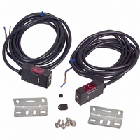
Photoelectric Sensor
Manufacturer
Omron
Series
E3S-Ar
Type
Photoelectric Sensorr
Specifications of E3S-AT61
Output Current
100mA
Sensor Output
NPN
Supply Voltage Range Dc
10V To 30V
Sensor Housing
Rectangular
Output Type
Transistor
Sensor Input
Optical
Sensing Range Max
7m
Mounting Type
Bracket
Sensing Distance
275.591" (7m)
Sensing Method
Through-Beam
Output Configuration
NPN - Dark-ON/Light-ON - Selectable
Current - Supply
40mA
Voltage - Supply
10 V ~ 30 V
Response Time
0.5ms
Package / Case
Module, Pre-Wired
Features
Control the laser with digital fiber amplifier
Height
21 mm
Length
45.3 mm
Maximum Operating Temperature
+ 55 C
Minimum Operating Temperature
- 25 C
Operating Supply Voltage
10 V to 30 V
Width
12.4 mm
Lead Free Status / RoHS Status
Lead free / RoHS Compliant
Lead Free Status / RoHS Status
Lead free / RoHS Compliant, Contains lead / RoHS compliant by exemption
Other names
E3SAT61
OR586
OR586
Available stocks
Company
Part Number
Manufacturer
Quantity
Price
Company:

Part Number:
E3S-AT61
Manufacturer:
OMRON
Quantity:
384


Unlike conventional photoelectric sensors, the variation in the sensitivity of E3S photoelectric sensors is minimal. This means the
sensitivity can be adjusted on only a single photoelectric sensor, and then the adjusters on the other photoelectric sensors can be set
to the same scale position. There is no need to adjust the sensitivity of each photoelectric sensor individually.
E3S-A
Installation
E3S Sensors equipped with the self-diagnostic feature incorpo-
rates an OFF-delay timer that can be adjusted within range of 0 to
100 ms.
The emitter of the through-beam sensor with the self-diagnostic
feature incorporates a turbo switch. When this switch is on, the
intensity of the red LED light source can be increased to make a
brighter spot. The OFF-delay time adjuster of the retroreflective
and the 20-cm diffuse reflective sensor is used as a turbo switch.
When the adjuster is pressed, it functions as a turbo switch to
automatically increase the power of the light source to create a
brighter light spot. Do not press the adjuster when turning it.
Turbo Function (Turbo Switch)
With the turbo function switched ON, the light spot is visible even
at a distance of 20 cm (7.87 in), making it easy to check the sensing
position and the angle of the optical axis.
1. After using the turbo function, readjust the OFF-delay time
Function
Sensing
Condition
Sensitivity
adjuster
Indicators
Procedure
Steps
that had been set, since the OFF-delay time could have
been changed when the turbo switch (which is on the OFF-
delay time adjuster) was pressed.
SENSITIVITY ADJUSTMENT
TIMER AND TURBO SWITCH
Place target at the desired
sensing distance. Set sensitivity
adjuster to the minimum scale
position, and gradually increase
sensitivity by turning the sensitiv-
ity adjuster clockwise until the
Light Incident indicator (red LED)
turns ON. Position A designates
the point at which the LED has
turned ON.
Step 1
Determine Position A
OFF
Photoelectric sensor
STABILITY
(green)
Min
A
ON
Sensing object
Max
LIGHT
(red)
Step 2
Remove the target. Starting from
the maximum scale position,
gradually decrease sensitivity by
turning the sensitivity adjuster
counterclockwise until the Light
Incident indicator (red LED) turns
OFF. Position B designates the
point at which the LED has turned
OFF.
Determine Position B
OFF
Photoelectric sensor
16
STABILITY
(green)
Min
Sensitivity adjuster
2. Press the OFF-delay time adjuster to switch ON the turbo
The turbo function is effective with the turbo switch pressed, and
the function is reset automatically when released.
With Turbo Switch ON
The OFF-delay
time adjuster is
used as a turbo
switch (black)
function with a maximum force of 1 kg and within a maximum
period of 3 minutes. (The photoelectric sensor, however, will
not malfunction even if the turbo function is switched on for
more than 3 minutes.)
OFF
Sensing object
Max
B
LIGHT
(red)
Visible spot
PUSH
Step 3
Set the sensitivity indicator to the
position between Positions A and
B (in some cases, Positions A
and B are opposite of the above
example). The photoelectric
sensor will then work normally if
the stability indicator (green) is lit
with and without the target. If it
is not lit, stable operation cannot
be expected, in which case a
different detection method should
be applied.
Adjust to optimum setting
Photoelectric sensor
ON
Normal Operating Condition
Min
A
STABILITY
(green)
Sensing object
OFF
Max
B
E3S-A
LIGHT
(red)
Related parts for E3S-AT61
Image
Part Number
Description
Manufacturer
Datasheet
Request
R

Part Number:
Description:
Sensor; Polarized Retroreflective Sensing Mode; Long Range Metal Body; 0 to 3 m
Manufacturer:
Omron Automation
Datasheet:
Part Number:
Description:
Sensor, Metal; NPN/PNP; Diffuse Mode Sensing Mode; Photoelectric; 27.56 in.
Manufacturer:
Omron Automation
Datasheet:
Part Number:
Description:
Sensor; NPN/PNP; Through-Beam Sensing Mode; Photoelectric; 30 m; 10 to 30 VDC
Manufacturer:
Omron Automation
Datasheet:
Part Number:
Description:
Sensor, Metal; NPN/PNP; Diffuse Mode Sensing Mode; Photoelectric; 27.56 in.
Manufacturer:
Omron Automation
Datasheet:

Part Number:
Description:
E3S-AT66 RECEIVER
Manufacturer:
Omron
Datasheet:

Part Number:
Description:
E3S-AT61 RECEIVER
Manufacturer:
Omron
Datasheet:
Part Number:
Description:
E3S-AT66 Emitter
Manufacturer:
Omron
Datasheet:
Part Number:
Description:
EMITTER ONLY FOR E3S-AT16
Manufacturer:
Omron
Datasheet:
Part Number:
Description:
RECEIVER ONLY FOR E3S-AT16
Manufacturer:
Omron
Datasheet:
Part Number:
Description:
RECEIVER ONLY FOR E3S-AT11
Manufacturer:
Omron
Datasheet:
Part Number:
Description:
G6S-2GLow Signal Relay
Manufacturer:
Omron Corporation
Datasheet:
Part Number:
Description:
Compact, Low-cost, SSR Switching 5 to 20 A
Manufacturer:
Omron Corporation
Datasheet:
Part Number:
Description:
Manufacturer:
Omron Corporation
Datasheet: