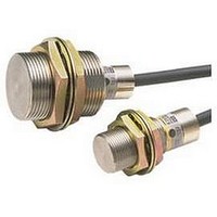
E2C-X1R5A Omron, E2C-X1R5A Datasheet - Page 6

E2C-X1R5A
Manufacturer Part Number
E2C-X1R5A
Description
Inductive Proximity Sensor
Manufacturer
Omron
Series
E2Cr
Specifications of E2C-X1R5A
Sensor Input
Inductive
Sensing Range
3mm
Switch Terminals
Cable
Sensor Output
NPN, NO/NC
Peak Reflow Compatible (260 C)
No
Sensor Housing
Rectangular
Size
M8
Sensing Range Max
1.5mm
Proximity Sensor Sensing Distance
1.5mm
Proximity Sensor Sensing Distance Range
<2mm
Mounting
Panel
Operating Temp Range
-25C to 70C
Operating Temperature Classification
Commercial
Pin Count
2
Maximum Operating Temperature
+ 70 C
Sensing Distance
1.5 mm
Minimum Operating Temperature
- 25 C
Sensor Type
Inductive
Sensing Object
Metallic
Response Frequency
800Hz
Material - Body
Brass
Shielding
Shielded
Voltage - Supply
-
Output Type
-
Terminal Type
2-Wire
Package / Case
Cylinder, Threaded - M8
Lead Free Status / RoHS Status
Contains lead / RoHS non-compliant
Cable Lengths for Sensor-Amplifier Unit Combinations
Standard Models
Note: The standard cable length is 3 m. Models with 5-m or 10-m are manufactured upon order.
* Refer to page 14 for the operation of cable length switching.
Heat-resistant Models
Note: The standard cable length is 3 m. Models with 5-m are manufactured upon order.
Self-diagnostic Function
The self-diagnostic output transistor will turn ON in the following cases. (The output will turn ON for any of these conditions individually.)
(1) Sensor open circuit: Transistor will turn ON the instance there is an open circuit for the Sensor (including the cable).
Sensor Open Circuit
(2) Detection:
(3) No detection: The output will turn ON if a sensing object is within 100% to 107% of the sensing distance continuously for 0.3 s or longer (e.g.,
Indicators
Amplifier Units
E2C-GE4A
E2C-GF4A
E2C-WH4A
E2C-JC4AP
E2C-JC4A
E2C-AM4A
E2C-AK4A
Amplifier Units
E2C-JC4CH
E2C-JC4DH
E2C-JC4EH
• The detection indicator lights when a sensing object approaches the
• The stability indicator lights when the sensing object approaches within
sensing distance to indicate that a sensing object has been detected.
93% of the sensing distance or moves away from 107% of the sensing
distance to indicate a stable sensing or non-sensing condition.
Sensing object
Control output
(NO)
Self-diagnostic
output
Detection indicator
(red)
Stability indicator
(green)
Present
Sensor
Sensor
OFF
OFF
OFF
OFF
None
ON
ON
ON
ON
The output will turn ON if a sensing object is within 93% to 100% of the sensing distance continuously for 0.3 s or longer (e.g.,
for sensing object position offset).
when background is influencing detection).
Red
E2C-CR8A E2C-CR8B
circuit
Open
E2C-X1R5AH
Open circuit
eliminated
Set 3 m/5 m cable length switch to desired position.
Set cable length switch to desired position.
Set cable length switch to desired position.
Red
Green
3 to 5 m: Open cable length terminals
1 to 3 m: Short cable length terminals
Restricted to 3 m or 5 m.
circuit
Open
Restricted to 3 m.
E2C-X1A
0 to 5 m
E2C-X2AH
Restricted to 3 m.
Open circuit
eliminated
E2C-C1A
Sensor Connected
E2C-X5AH
*
*
Control output
(NO)
Self-diagnostic
output
Detection indicator
(red)
Stability indicator
(green)
indicator (red)
Set distance:
Detection
X1R5A
E2C-
Sensing distance:
*
*
Note: When the E2C-X2A Sensor is used, 93% is 96% and 107% is 104%.
* The self-diagnostic output may turn ON if the sensing objects moves a low
OFF
ON
speed. In actual application, include an ON-delay timer circuit or other
suitable measure.
Approx. 107%
Approx. 97%
100%
OFF
OFF
OFF
OFF
E2C-X2A
ON
ON
ON
ON
(green)
Stability indicator
Set cable length switch to desired position.
---
---
---
ON
0.3 s min.
OFF
ON
Green
*
E2C-X5A
Set distance × Approx. 1.07*
Set distance
Set distance × Approx. 0.93*
* When the E2C-X2A Sensor is used,
107% is 104% and 93% is 96%.
---
---
---
---
---
0 to 10 m
Red
Green
E2C-X10A
E2C/E2C-H
0.3 s min.
---
---
---
---
---
*
C20MA
E2C-
---
---
---
---
---
Green
Time
*
6


