55110 3M 02 A HAMLIN, 55110 3M 02 A Datasheet
55110 3M 02 A
Manufacturer Part Number
55110 3M 02 A
Description
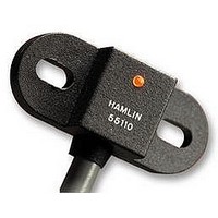
SENSOR, HALL EFFECT, FLANGE MOUNT
Manufacturer
HAMLIN
Datasheet
1.55110_3M_02_A.pdf
(1 pages)
Specifications of 55110 3M 02 A
Sensor Terminals
Tinned Lead
Output Voltage
0.4VDC
Supply Voltage Range Dc
3.8V To 24V
Output Configuration
Sink
Switching Speed
0.1ms
Sensing Range
0mm To 12.5mm
Frequency Response Max
10kHz
SK 55110 DATA SHEET.qxd
Hamlin USA
Hamlin UK
Hamlin Germany Tel: +49 (0) 6181 953660
Hamectrol France Tel: +33 (0) 1 4687 0202
Issue No: 3 Date: 24/03/03 DCR B0063
TABLE 1
SPECIFICATIONS
Hall Type
DIMENSIONS (in) mm
CUSTOMER OPTIONS - Switching Specifications
CUSTOMER OPTIONS - Sensitivity, Cable Length and Termination Specification
ORDERING INFORMATION
Supply Voltage
(Note 1)
Output High Voltage
Output Low Voltage
Output Current (continuously on)
Switching Speed
Temperature
Note 1 - As long as Tj (Junction Temperature) max. is not exceeded
HALL OPTIONS
ACTIVATE DISTANCES ARE APPROXIMATE
USING
(.827L
HAMLIN P
Hall Option
Select
3M
3H
3L
N
X
/
.276W
E
N
F
(.157)
4.00
5812334000
E
B
(.394)
10.00
MAGNET
X
.185H) 21
Tel: +1 920 648 3000
Tel: +44 (0)1379 649700
3 Wire Switch
3 Wire Switch
3 Wire Latch
Absolute Ratings
Operate
Overvoltage Protection
Operating
Storage
Type
Hall
X
7
9/4/03
X
4.7
Series 55110
Hall option
Cable Length
Termination
55110 L.E.D. Flange Mount Hall Effect Sensor Features and Benefits
Features
•
•
•
•
•
•
•
•
•
•
•
Magnetically operated position sensor
Digital or latching types available
Integral LED
Medium or high sensitivities
3 wire (voltage output)
Vibration 50g max. @ 50-2,000Hz
Shock 150g max. @ 11ms
EMC to DIN 40839 (Consult Hamlin)
Reverse/Over Voltage Protection
Built in temperature compensation
Fax: +1 920 648 3001
•
•
•
Not including encapsulant
Gauss (Typ.)
Fax: +44 (0)1379 649702
Fax: +33 (0) 1 4686 6786
Sensitivity
Fax: +49 (0) 6181 9536666
12:39 pm
130
(.551)
14.00
59
86
Vdc
Vdc
Vdc-max
Vdc-min
Vdc-max
mA-max
kHz-max
O
O
C
C
N
Slot (.138 x .256)
3.50 x 6.50 Typ.
S
Table 1
Table 2
Table 3
•
Page 1
Integral L.E.D.
Email: sales.us@hamlin.com
Activate - d
Table 2 ±(.393) 10.00
(.492) 12.5
(.709) 18.0
(.394) 10.0
(in) mm
d
•
•
Email: sales.uk@hamlin.com
Email: sales.fr@hamlin.com
1
•
/
2
Email: sales.de@hamlin.com
Sine
55110
TABLE 2
Cable Length:-
(Cable type 24 AWG 7/32 PVC
105
SELECT
OPTION
Benefits
•
•
•
•
•
•
o
(.250)
6.35 Nom.
01
02
03
04
05
C Double Insulated)
High switching speed up to 10kHz
Long life; up to 20 billion operations
Visual indication of operation
Unaffected by harsh environments
Operates in static or dynamic magnetic
field
Customer selection of cable length and
connector type
XX
LENGTH
(in)
(39.37) 1000
(11.81) 300
(19.69) 500
(29.53) 750
Vdd-2 @ 0.1mA (sinking output with internal pull-up)
(3.94) 100
mm
XX
Digital Switch or Digital Latch
BLOCK DIAGRAMS
Note
Add capacitor Cn as
shown, close for the
sensor, for transient
suppression if required
Cn
(Black)
(Red)
(Voltage output)
Pin 1
GND
Pin 2
VDD
TABLE 3
DETAILS PROVIDED ON THIS DATA SHEET ARE PROVIDED FOR
INFORMATION PURPOSES ONLY AND SHOULD NOT BE RELIED
UPON AS BEING ACCURATE FOR ANY PARTICULAR PURPOSE.
Product performance may be affected by the application to which the
product is put. Upon request, HAMLIN will assist purchasers by
providing information specific to any particular application. HAMLIN
disclaims any and all liability whatsoever for any purchaser’s reliance
upon the information contained on this data sheet without further
consultation with authorised representatives of HAMLIN.
0.4 @ 10mA
+3.8 to +24
-40 to +100
-65 to +105
-15 to +28
X
Termination Options:-
OPTION
3 Wire
SELECT
32
10
10
A
B
C
D
E
Plate
Hall
Switch
DESCRIPTION
Tinned leads
Crimped terminals
6.35mm fastons
AMP MTE 2.54mm pitch
JST XHP 2.5mm pitch
Applications
•
•
•
•
•
•
Position and limit sensing
RPM measurement
Flow metering
Commutation of brushless dc motors
Angle sensing
Magnetic encoders
Comparator
Clock
www.hamlin.com
Output
(Blue)
Pin 3
OUT
Related parts for 55110 3M 02 A
Image
Part Number
Description
Manufacturer
Datasheet
Request
R

Part Number:
Description:
SENSOR HALL EFFECT W/LED PNL MNT
Manufacturer:
Hamlin Electronics Limited Partnership
Datasheet:

Part Number:
Description:
Manufacturer:
Hamlin Electronics
Datasheet:

Part Number:
Description:
RELAY REED DIP SPDT-CO 12V
Manufacturer:
Hamlin Electronics Limited Partnership
Datasheet:
Part Number:
Description:
RELAY REED DIP SPDT-CO W/DIO 5V
Manufacturer:
Hamlin Electronics Limited Partnership
Datasheet:
Part Number:
Description:
RELAY REED DIP SPDT-CO W/DIO 12V
Manufacturer:
Hamlin Electronics Limited Partnership
Datasheet:

Part Number:
Description:
RELAY REED SIP SPST 5V W/DIODE
Manufacturer:
Hamlin Electronics Limited Partnership
Datasheet:
Part Number:
Description:
TEST COIL FOR REED SWITCH, 1PC
Manufacturer:
Hamlin Electronics Limited Partnership

Part Number:
Description:
TEST COIL FOR REED SWITCH, 1PC
Manufacturer:
Hamlin Electronics Limited Partnership


Part Number:
Description:
LED 3MM HIGH EFF GREEN
Manufacturer:
Dialight
Datasheet:

Part Number:
Description:
LED 3MM HIGH EFF RED
Manufacturer:
Dialight
Datasheet: