A16ZJ-5050 Omron, A16ZJ-5050 Datasheet - Page 44
A16ZJ-5050
Manufacturer Part Number
A16ZJ-5050
Description
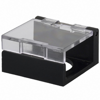
SWITCH GUARD RECTANGULAR
Manufacturer
Omron
Series
A16Zr
Type
Pushbutton Switches/Pilot Lightsr
Specifications of A16ZJ-5050
Rohs Compliant
YES
Accessory Type
Switch Guard
Application
Wide range of switching Capacity from general to microload
Features
Terminal layout simplifies common wiring
Color
Red
Lead Free Status / RoHS Status
Lead free / RoHS Compliant
For Use With/related Products
A16 Series
For Use With
Z1392 - SWTCH KNOB RND 2POS SPDT ILL YLWZ1391 - SWTCH KNOB RND 2POS SPDT ILL REDZ1390 - SWTCH KNOB RND 2POS SPDT ILL GRNZ1387 - SWITCH KNOB RND 2-POS SPDTZ1386 - SWITCH KNB RECT 3POS DPDT ILLZ1385 - SWITCH KNB RECT 3POS DPDT ILLZ1384 - SWITCH KNB RECT 3POS DPDT ILLZ1383 - SWITCH KNB RECT 2POS SPDT ILLZ1382 - SWITCH KNB RECT 2POS SPDT ILLZ1381 - SWITCH KNB RECT 2POS SPDT ILLZ1380 - SWITCH KNB RECT 2POS SPDT ILLZ1379 - SWITCH KNB RECT 2POS SPDT ILLZ1378 - SWITCH KNB RECT 2POS SPDT ILLZ1377 - SWITCH KNOB RECT 3-POS DPDTZ1376 - SWITCH KNOB RECT 2-POS SPDTZ1322 - SWITCH PB RECT MOM DPDT YELLOWZ1321 - SWITCH PB RECT MOM DPDT WHITEZ1320 - SWITCH PB RECT MOM DPDT REDZ1319 - SWITCH PB RECT MOM DPDT GREENZ1318 - SWITCH PB RECT MOM DPDT BLACKZ1307 - SWITCH PB RECT MOM DPDT ILLUMZ1306 - SWITCH PB RECT MOM DPDT ILLUMZ1305 - SWITCH PB RECT MOM DPDT ILLUMZ1304 - SWITCH PB RECT MOM DPDT ILLUM
Lead Free Status / Rohs Status
Lead free / RoHS Compliant
Other names
A16ZJ5050
Z1338
Z1338


Correct Use
J NUT MOUNTING
Insert the buzzer unit from the front of the panel and tighten the
mounting nut inserted from the rear of the panel.
Since a projection exists on the rear portion of the buzzer unit, if
the mounting nut cannot be fitted into position, turn the nut
slightly.
The tightening torque of the mounting nut should be less than
5 kg-cm.
Solder the terminals after mounting the nut. Otherwise, the
terminals, when thickened by solder, may prevent the nut from
being screwed down onto the buzzer unit.
J MOUNTING
Tighten the mounting nut at a torque of less than 5 kg-cm.
J WIRING
Exercise caution that the input terminals are not short-circuited
by the short-circuiting jumper.
Finish soldering within 5 seconds with a 30 watt soldering iron, or
within 3 seconds at a solder temperature of 240°C. For about a
minute after soldering, do not apply any force to the buzzer unit,
to avoid deforming the softened plastic buzzer unit base.
Use an non-corrosive, resin-based soldering flux.
J SNAP-IN MOUNTING
Attach the mounting leaf spring to the buzzer. Engage the edges
of the leaf spring in the two grooves on the threaded section of
the buzzer. After inserting the leaf spring edges into the grooves,
confirm that the leaf spring has seated. Be sure to attach both
leaf springs.
Insert the buzzer assembly into the hole on the mounting panel
from the front.
M2BJ-B
45
J SHORT-CIRCUITING JUMPER
The buzzer sounds continuously or intermittently depending on
how the short-circuiting bracket is attached to the case guide.
When the bracket is attached with the triangle on it facing
direction A (PC board side), the buzzer sounds intermittently.
To produce continuous sounds, attach the bracket to the case
guide so that the triangle on the bracket faces direction B.
M2BJ-B
Related parts for A16ZJ-5050
Image
Part Number
Description
Manufacturer
Datasheet
Request
R

Part Number:
Description:
LEGEND PANEL ROUND TRANSPARENT
Manufacturer:
Omron
Datasheet:
Part Number:
Description:
LEGEND PANEL RECTANGULAR OPAQUE
Manufacturer:
Omron
Datasheet:
Part Number:
Description:
LEGEND PANEL IP40 RECT TRANSP
Manufacturer:
Omron
Datasheet:

Part Number:
Description:
PANEL PLUG RECTANGULAR
Manufacturer:
Omron
Datasheet:
Part Number:
Description:
CAP 16 SERIES RECTANGULR LED GRN
Manufacturer:
Omron
Datasheet:
Part Number:
Description:
CAP 16 SERIES RECTANGULAR BLACK
Manufacturer:
Omron
Datasheet:
Part Number:
Description:
CAP 16 SERIES RECTANGULAR GREEN
Manufacturer:
Omron
Datasheet:
Part Number:
Description:
CAP 16 SERIES RECTANGULAR BLACK
Manufacturer:
Omron
Datasheet:
Part Number:
Description:
IP40 COLOR CAP REC BLUE
Manufacturer:
Omron
Datasheet:
Part Number:
Description:
IP40 COLOR CAP REC GREEN
Manufacturer:
Omron
Datasheet:

Part Number:
Description:
SWITCH PB SQUARE MOM SPDT GREEN
Manufacturer:
Omron
Datasheet:
Part Number:
Description:
SWITCH PB SQUARE MOM SPDT WHITE
Manufacturer:
Omron
Datasheet:
Part Number:
Description:
SWITCH PB SQUARE MOM SPDT YELLOW
Manufacturer:
Omron
Datasheet:
Part Number:
Description:
SWITCH PB RECTANG MOM SPDT BLUE
Manufacturer:
Omron
Datasheet:
Part Number:
Description:
SWITCH PB RECTANG MOM SPDT YEL
Manufacturer:
Omron
Datasheet: