863093C15ALF FCI, 863093C15ALF Datasheet - Page 68
863093C15ALF
Manufacturer Part Number
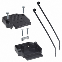
863093C15ALF
Description
BACKSHELL DB15 90DEG PLASTIC
Manufacturer
FCI
Specifications of 863093C15ALF
Accessory Type
Two Piece Backshell
Number Of Positions
15
Cable Type
Flat
Cable Exit
90°
Shielding
Unshielded
Hardware
Assembly Hardware, Strain Relief
Color
Black
Product
Standard Hoods & Connectors
Number Of Positions / Contacts
15
Gender
Female
Mounting Style
Cable
Mounting Angle
Straight
Termination Style
Screw
Rohs Compliant
YES
For Use With
DAMF15SN - DSUB DM SIG STB 15 SOCKDAM15SN - DSUB DM SIG STB 15 SOCKDAM15PN - DSUB DM SIG STB 15 PINDAMF15PN - DSUB DM SIG STB 15 PINDAL11W1P043A00LF - DSUB POWER STB 11W1 PINDA11W1S043A00LF - DSUB POWER STB 11W1 SOCKDA11W1SA00LF - DSUB POWER STB 11W1 SOCKDAML15P - DSUB DM SIG STB 15 PINDA11W1PA00LF - DSUB POWER STB 11W1 PINDA7W2S043A00LF - DSUB POWER STB 7W2 SOCKETDAMF11W1SN - DSUB DM POWER 11W1 SOCKDAMF15P - DSUB DM SIG STB 15 PINDA15P065TXLF - DSUB SIGNAL STC 15PINDAM11W1SN - DSUB DM POWER 11W1 SOCKDA15S065TLF - DSUB SIGNAL STC 15SOCKETDAM11W1PN - DSUB DM POWER 11W1 PINDAM7W2PN - DSUB DM POWER 7W2 PINDAM7W2SN - DSUB DM POWER 7W2 SOCKET609-2811 - CONN DSUB SOCKET 15POS SOLDR CUP609-2810 - CONN DSUB PLUG 15POS SOLDER CUP609-1517 - CONN DSUB POWER RECEPT 7W2 A609-1516 - CONN DSUB POWER PLUG 7W2 A609-1513 - CONN DSUB RECEPT 15POS SOLDERCUP609-1512 - CONN DSUB PLUG 15POS SOLDERCUP609-1469 - CONN DSUB FEMAL 15POS CRIMP GOLD609-1468 - CONN DSUB MALE 15POS CRIMP GOLD
Lead Free Status / RoHS Status
Lead free / RoHS Compliant
Features
-
Plating
-
Lead Free Status / Rohs Status
Lead free / RoHS Compliant
Other names
609-1431


SHELL DIMENSIONS
PC CARD DRILLING DIMENSIONS
(for solder versions)
Note: Ø A= 0.8 min. for D, DP
Note: Ø A= 0.9 min. for Delta D, Compact D, HE501, HE507, HE508 and DP US footprint
D-Sub Technical Characteristics
Note: pitch between row= 2.84 for straight spills
68
E
A
B
C
D
P
S
P
S
P
S
P
S
P
S
A
30.81
30.81
39.14
39.14
53,03
53,03
69.32
69.32
66.93
66.93
± 0.38
B
16.91
16.33
25.24
24.66
38.96
38.37
55.42
54.83
52.80
52.42
± 0.13
View of mating faces
External dimensions
of female connector
of male connector
Inside dimensions
C
24.99
24.99
33.32
33.32
47.04
47.04
63.50
63.50
61.11
61.11
± 0.13
D
11.20
10.74
8.35
7.89
8.35
7.89
8.35
7.89
8.35
7.89
± 0.13
(mm)
12.55
12.55
12.55
12.55
12.55
12.55
12.55
12.55
15.37
15.37
E
± 0.38
F Max.
10.99
11.21
10.99
11.21
11.07
11.21
11.09
11.21
11.09
11.21
G
5.85
6.05
5.85
6.05
5.75
6.05
5.75
6.05
5.75
6.05
+ 0.25
- 0
H
19.27
19.27
27.50
27.50
41.27
41.27
57.70
57.70
55.32
55.32
± 0.25
10.71
10.71
10.71
10.71
10.71
10.71
10.71
10.71
13.56
13.56
J
± 0.25
K Max.
1.50
1.50
1.50
1.50
1.50
1.50
1.50
1.50
1.70
1.50
L
0.90
0.90
0.90
0.90
0.90
0.90
1.00
0.90
1.00
0.90
± 0.12
Related parts for 863093C15ALF
Image
Part Number
Description
Manufacturer
Datasheet
Request
R

Part Number:
Description:
(FCI-HR005 - FCI-HR040) Large Active Area and High Speed Silicon Photodiodes
Manufacturer:
Laser Components
Datasheet:
Part Number:
Description:
(FCI-INGAAS-55 - FCI-INGAAS-500) High Speed InGaAs Photodiodes
Manufacturer:
Laser Components
Datasheet:
Part Number:
Description:
Door, lock & key
Manufacturer:
GAMEWELL-FCI [Gamewell-FCI by Honeywell]
Datasheet:
Part Number:
Description:
30485Fire Fighter Phone Accessories
Manufacturer:
GAMEWELL-FCI Gamewell-FCI by Honeywell
Datasheet:

Part Number:
Description:
Manufacturer:
FCI
Datasheet:
Part Number:
Description:
Manufacturer:
FCI
Datasheet: