CA016 71 0002 Amphenol-Tuchel Electronics, CA016 71 0002 Datasheet - Page 27
CA016 71 0002
Manufacturer Part Number
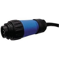
CA016 71 0002
Description
CIRCULAR FEMALE CONNECTOR CABLE, 10FT
Manufacturer
Amphenol-Tuchel Electronics
Datasheet
1.CA_016_70_0001.pdf
(32 pages)
Specifications of CA016 71 0002
Connector Type A
Circular Receptacle
Connector Type B
Stripped End Leads
No. Of Branches
1
Cable Assembly Type
Circular Industrial
Cable Length
10ft
No. Of Contacts
3
Lead Free Status / RoHS Status
Lead free / RoHS Compliant


Amphenol
1)
2)
3)
Style
Male cable connector
Female cable connector
Male receptacle
screw / crimp
Female receptacle
screw / crimp
C16-3
Remarks
Safety classification
Pollution degree 3: Conductive pollution occurs or dry non-conductive pollution occurs which becomes conductive due to condensation which is to be expected.
Protection against electrical shock on the termination side has to be secured by proper mounting.
1. General Remarks
These connectors are designed and produced in conformity with the
low voltage directive (73/23/EWG) respectively Gerätesicherheitsgesetz
(German law) and are especially in according with the standards
DIN EN 61984 / IEC 61984 (VDE 0627); IEC 60664-1 (VSE 0110-1) and
IEC 60529. The connectors may be used only within the technical ratings.
These connectors with / without breaking capacity are designed and
produced according to DIN EN 61984/VDE0627.
All technical data refers to mated connectors under live conditions.
The safety of the connector system depends on the correct selection of
products, proper assembly of the connector device, and a precise fit of the
connectors.
2. Application Remarks
Connectors with / without breaking capacity must be used according to
specified technical ratings.
The technical data represents the initial value of mated parts under
predetermined conditions and length of time.These values could change
with different test parameters or product requirements.
The 16-3 Series connectors are used in a wide variety of industries and
equipment. Some of these include industrial machines and controls,
data processing, instrumentation and test equipment, medical devices,
telecommunication’s network and equipment, plus outdoor and marine
applications.
All rated data for the connectors listed in this catalogues are based
on over-voltage category III
applications.
5. Safety Classification acc. to DIN EN 61984 / VDE 0627 / IEC 61984
Overvoltage category III: Equipment intended for the use in installations or parts of it in which lightning overvoltages do not need to be considered,
however switching overvoltages generated by the equipment, and for cases where the reliability and the availability of the equipment or its dependent
circuits are subject to special requirements. Examples are protecting means, switches and sockets.
1)
X
X
X
X
and pollution degree 3
3)
3)
X
X
2)
for electronic
X
X
X
X
X
X
X
X
3)
3)
Connectors were completely mated according to their respective safety
locking mechanism. Selection and testing of connectors with / without
breaking capacity to meet specific product or industrial requirements such
as rated voltage and the related clearances and creepage distances are the
responsibility of the user.
3. Assembling Remarks
Protection against electrical shock of the termination of the connectors
shall be secured by correct mounting. Connectors of the same or different
series being mounted side by side may be protected against incorrect
mating by the use of coding options. Care must be taken to ensure the
parts are correctly mated and screws are tightened with the proper torque.
4. Termination Remarks
Cable connectors are effectively secured when using the internal cable
clamp. When the connector contains a simple gland bushing for retention
without clamping ring the cable should have a strain relief close behind
the connector. All cable properties or specifications must be compatible
with the connector design and materials.
Designated wire conductors must be terminated to the correct poles in the
connector.
Crimp contacts must be fully inserted into the plastic housing and
retention assured with a slight tug on the wire.
Wire should be stripped correctly according to printed specifications to
insure no electrical contact can be made between the conductors. There
should be no nicked or cut strains during the stripping action.
X
X
3)
X
X
X
X
X
X
X
X
X
X
X
X
Cable clamp
with
X
X
without
X
X
X
X
27
Related parts for CA016 71 0002
Image
Part Number
Description
Manufacturer
Datasheet
Request
R

Part Number:
Description:
Male Receptacle 8+PE
Manufacturer:
Amphenol-Tuchel Electronics
Datasheet:

Part Number:
Description:
CBL ASSY 10' FMALE 8POS SGL C091
Manufacturer:
Amphenol-Tuchel Electronics
Part Number:
Description:
CONN MALE REAR PNL MT 3POS 0.5M
Manufacturer:
Amphenol-Tuchel Electronics
Datasheet:
Part Number:
Description:
CABLE ASSY MALE SNGL END 3POS 2M
Manufacturer:
Amphenol-Tuchel Electronics
Datasheet:
Part Number:
Description:
CONN FEMALE REAR PNL MT 4POS .5M
Manufacturer:
Amphenol-Tuchel Electronics
Datasheet:
Part Number:
Description:
CABLE ASSY R/A MALE SNGL 3POS 2M
Manufacturer:
Amphenol-Tuchel Electronics
Datasheet:
Part Number:
Description:
CONN MALE FRONT PNL MT 5POS .5M
Manufacturer:
Amphenol-Tuchel Electronics
Datasheet:
Part Number:
Description:
CONN MALE 3POS FRONT PNL MT .5M
Manufacturer:
Amphenol-Tuchel Electronics
Datasheet:
Part Number:
Description:
CONN MALE REAR PNL MT 4POS 0.5M
Manufacturer:
Amphenol-Tuchel Electronics
Datasheet:
Part Number:
Description:
CABLE ASSY MALE SNGL END 3POS 2M
Manufacturer:
Amphenol-Tuchel Electronics
Datasheet:
Part Number:
Description:
Male Receptacle 8+PE
Manufacturer:
Amphenol-Tuchel Electronics
Datasheet:

Part Number:
Description:
MEMORY CARD CONNECTOR, SMARTCARD
Manufacturer:
Amphenol-Tuchel Electronics
Datasheet:
Part Number:
Description:
Female Receptacle 8+PE
Manufacturer:
Amphenol-Tuchel Electronics
Part Number:
Description:
Male Cable Connector
Manufacturer:
Amphenol-Tuchel Electronics
Part Number:
Description:
Male Cable Connector
Manufacturer:
Amphenol-Tuchel Electronics