XF2G-1614-11 Omron, XF2G-1614-11 Datasheet - Page 2
XF2G-1614-11
Manufacturer Part Number
XF2G-1614-11
Description
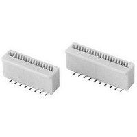
CONN FPC 16POS 0.5MM SMT
Manufacturer
Omron
Series
XF2Gr
Type
FPC Connectorr
Datasheet
1.XF2G-0614-11.pdf
(4 pages)
Specifications of XF2G-1614-11
Contact Plating
Tin Alloy on Nickel
Connector Type
Vertical Contacts, 1 Sided
Number Of Positions
16
Pitch
0.020" (0.50mm)
Ffc, Fcb Thickness
0.30mm
Height Above Board
0.163" (4.15mm)
Mounting Type
Surface Mount
Cable End Type
Tapered
Termination
Solder
Contact Finish
Tin
Contact Finish Thickness
79µin (2.00µm)
Operating Temperature
-30°C ~ 85°C
Current Rating
0.500A
Voltage Rating
50V
Housing Material
Polyamide (PA46), Nylon 4/6
Contact Gender
HDR
Mounting Style
Surface Mount
Number Of Contact Rows
2
Number Of Contacts
16POS
Pitch (mm)
1mm
Body Orientation
Straight
Contact Resistance Max
30mOhm
Voltage Rating Max
50VDC/50VAC
Operating Temp Range
-30C to 85C
Current Rating (max)
0.5A
Housing Color
Natural
Contact Material
Copper Alloy
Termination Method
Solder
Product Height (mm)
4.15mm
Product Depth (mm)
2.95mm
Product Length (mm)
9.9mm
Gender
Receptacle
Pitch Spacing
0.5mm
No. Of Contacts
16
No. Of Rows
2
Ffc/fpc Thickness
0.3mm
Contact Termination
Surface Mount Vertical
Lead Free Status / RoHS Status
Contains lead / RoHS non-compliant
Features
-
Locking Feature
-
Lead Free Status / RoHS Status
Contains lead / RoHS non-compliant, Contains lead / RoHS non-compliant
Other names
OR674TR
XF2G161411
XF2G161411


Dimensions
Unit: mm
XF2G-@@14-11
■ Tape and Reel Dimensions
330
(12.99)
dia.
2
Table of Dimensions
Pins Model
3 (0.118)
14
16
24
26
6
80 (3.15) dia.
XF2G-0614-11
XF2G-1414-11
XF2G-1614-11
XF2G-2414-11 13.9 12.5 11.5
XF2G-2614-11 14.9 13.5 12.5
Non-ZIF Type (0.5 mm-pitch)
A
B
A
4.9
8.9
9.9
B
3.5
7.5
8.5
C
2.5
6.5
7.5
0.2
Direction of
drawout
0.5
XF2G
A
B
C
C D
4.15
1.3 (0.051)
3.5 (0.138)
2.4
3.4
2.95
4.4±0.1
(0.173)
Printed Circuit Board Matching Dimensions (Top View)
4±0.1
(0.157)
0.5
2 (0.079)
±0.1
2.8
1.36 (0.054)
2.6 (0.102)
Applicable FPC Dimensions
E
0.5
12±0.1
(0.472)
Direction of
drawout
±0.03
C
(Conductive plating)
B
C
1.5
(0.055)
dia.
B
±0.05
±0.07
±0.05
T=0.3
+0.1
0.35
0
±0.03
±
0.05
0.5
1.75±0.1
(0.069)
11.5±0.1
(0.453)
±0.05
1.6
1.6
0.5
(reinforcement
4
±0.05
board)
E
5
Related parts for XF2G-1614-11
Image
Part Number
Description
Manufacturer
Datasheet
Request
R

Part Number:
Description:
CONN FPC 6POS 0.5MM SMT
Manufacturer:
Omron
Datasheet:
Part Number:
Description:
CONN FPC 14POS 0.5MM SMT
Manufacturer:
Omron
Datasheet:

Part Number:
Description:
G6S-2GLow Signal Relay
Manufacturer:
Omron Corporation
Datasheet:
Part Number:
Description:
Compact, Low-cost, SSR Switching 5 to 20 A
Manufacturer:
Omron Corporation
Datasheet:
Part Number:
Description:
Manufacturer:
Omron Corporation
Datasheet:
Part Number:
Description:
Manufacturer:
Omron Corporation
Datasheet:
Part Number:
Description:
Manufacturer:
Omron Corporation
Datasheet:
Part Number:
Description:
Manufacturer:
Omron Corporation
Datasheet:
Part Number:
Description:
Manufacturer:
Omron Corporation
Datasheet:
Part Number:
Description:
Manufacturer:
Omron Corporation
Datasheet: