N7E50-7516PG-20 3M, N7E50-7516PG-20 Datasheet - Page 3
N7E50-7516PG-20
Manufacturer Part Number
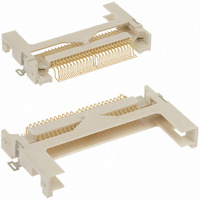
N7E50-7516PG-20
Description
CF CARD HEADER TYPE I SMD
Manufacturer
3M
Series
7E50r
Type
Ir
Specifications of N7E50-7516PG-20
Card Type
Compact Flash - Type I
Number Of Positions
50
Connector Type
Connector
Insertion, Removal Method
Push In, Pull Out
Mounting Type
Surface Mount, Right Angle
Features
Board Guide, Card Guide
Height Above Board
0.261" (6.64mm)
Mounting Feature
Normal, Standard - Top
Contact Finish
Gold
Contact Finish Thickness
Flash
Product
Headers
Rohs Compliant
Yes
Lead Free Status / RoHS Status
Lead free / RoHS Compliant
Ejector Side
-
Lead Free Status / Rohs Status
Lead free / RoHS Compliant
Other names
05111165508
3M5438
4547452459421
54745245942
JE150339370
N7E50-7516PG-20
N7E507516PG20
3M5438
4547452459421
54745245942
JE150339370
N7E50-7516PG-20
N7E507516PG20
Available stocks
Company
Part Number
Manufacturer
Quantity
Price
Company:

Part Number:
N7E50-7516PG-20-WF
Manufacturer:
NAIS
Quantity:
1 179


3M
.100” × .100” Latch/Ejector, Straight and Right Angle
3
Electronic Solutions Division
Interconnect Solutions
http://www.3Mconnector.com
Notes:
1. Notches A & C will accomodate 3M Polarizing Keys (3M Part #3518 or N3518).
2. Accepts Rear and Front mounting hardware:
3. The recommended PCB hole size for the kinked tail positions on the .112 solder tail connector is .035 ± .002.
Rear Entry: #4-24 thread cutting screw, 3M Part #3341-5, .116 [2.95] dia mounting hole
Front Entry: (Prior to installation of latch on Straight Versions) #2-56 bolt and nut, 3M Part #3341-6,
.106 [2.69] dia mounting hole
Kink is located .05” below bottom surface of plastic. External radius of kink toward part centerline
™
“Y”
Three-Wall Header
Number Suffix
.100 ± .003
[2.54]
C L
3M Part
[1.52]
.060
-1XX2
-2XX2
-1X03
-2X03
Pin Qty
.300
[7.62]
Side to Side Stackability
Recommended Mounting Hole Pattern
10
14
16
20
26
34
40
50
60
64
0.94 (2.39) to .125
Thick PC Board
(3.18) Thick PC
Contact Tail
Solder Tail for
Solder Tail for
.062 (1.57)
Number
3M Part
Board
3793
3314
3408
3428
3429
3431
3432
3433
3372
3764
Ø.106
Position 1
[2.69]
(Straight)
.100 ± .003
[2.54]
(See Note 2)
B
[8.94]
.352
or
1.26 (32.1)
1.46 (37.2)
1.76 (44.8)
2.46 (62.6)
2.76 (70.2)
3.96 (100.7)
1.56 (39.7)
2.06 (52.4)
3.26 (82.9)
3.76 (95.6)
G Dim
Dimension E
A
Ø.116
[2.95]
(2.84)
(3.94)
.112
.155
1.105 (28.07)
1.305 (33.15)
1.405 (35.69)
1.605 (40.77)
1.905 (48.39)
2.305 (58.55)
2.605 (66.17)
3.105 (78.87)
3.605 (91.57)
3.805 (96.65)
Dimension F
.0245 ± .0005
.0245 ± .0005
Table 2
B
Table 1
(0.622)
(0.622)
Dimensions
Pin Cross Section
“Y”
0.865 (21.97)
1.065 (27.05)
1.165 (29.59)
1.365 (34.67)
1.665 (42.29)
2.065 (52.45)
2.365 (60.07)
2.865 (72.77)
3.365 (85.47)
3.565 (90.55)
Diagonals
.028 ± .001
.028 ± .001
(0.71)
(0.71)
C
.100 ± .003
[2.54]
C L
[0.74]
.029
For technical, sales or ordering information call
Recommended Mounting Hole Pattern
.41
[10.4]
Max to Edge of PCB
for Daisy Chain
Corner Radii
0.71 (18.0)
0.91 (23.1)
1.01 (25.6)
1.21 (30.7)
1.51 (38.3)
1.91 (48.5)
2.21 (56.1)
2.71 (68.8)
3.21 (81.5)
3.41 (86.6)
.0075 Ref
.0075 Ref
(0.191)
(0.191)
D
3M is a trademark of 3M Company.
(Right Angle)
Ø.106
.100 ± .003
[2.54]
[2.69]
Position 1
(See Note 2)
Polarizing
Notches
(0.89) (See Note 3)
0.035 ± .003 (0.89)
ABC
ABC
ABC
ABC
ABC
ABC
ABC
ABC
Dimension G
BC
BC
Inch
[5.89]
.232
C
Tolerance Unless Noted
0.035 ± .003
or
G Dim
[ ] Dimensions for
Reference only
Ø.116
± .1
[2.95]
.0
(mm)
Inch
3000 Series
± .01
800-225-5373
.00
Sheet 3 of 5
TS-0771-E
± .005
.000
Related parts for N7E50-7516PG-20
Image
Part Number
Description
Manufacturer
Datasheet
Request
R

Part Number:
Description:
CF CARD HEADER TYPE I SMD INVRSE
Manufacturer:
3M
Datasheet:

Part Number:
Description:
CF CARD HEADER TYPE I SMD
Manufacturer:
3M
Datasheet:

Part Number:
Description:
CF CARD HEADER TYPE I SMD INVRSE
Manufacturer:
3M
Datasheet:

Part Number:
Description:
CF CARD HEADER TYPE II SMD
Manufacturer:
3M
Datasheet:

Part Number:
Description:
CF CARD HEADER TYPE II SMD INVTD
Manufacturer:
3M
Datasheet:

Part Number:
Description:
3M-MINI-CLAMP/PLUG/WMIC/2MM/3POS/TYPE A/ORANGE/3M LOGO
Manufacturer:
3M
Datasheet:
Part Number:
Description:
3M-MINI-CLAMP/PLUG/WMIC/2MM/4POS/TYPE A/YELLOW/3M LOGO
Manufacturer:
3M
Datasheet:
Part Number:
Description:
3M-MINI-CLAMP/PLUG/WMIC/2MM/4POS/TYPE A/ORANGE/3M LOGO
Manufacturer:
3M
Datasheet:
Part Number:
Description:
3M-MINI-CLAMP/SKT PANELMOUNT/WMIC/2MM/3POS/TYPE A/RED/3M LOGO
Manufacturer:
3M
Datasheet:
Part Number:
Description:
3M-MINI-CLAMP/SKT PANELMOUNT/WMIC/2MM/3POS/TYPE A/YELLOW/3M LO
Manufacturer:
3M
Datasheet:
Part Number:
Description:
3M-MINI-CLAMP/SKT/WMIC/2MM/3POS/TYPE A/ORANGE/3M LOGO
Manufacturer:
3M
Datasheet:
Part Number:
Description:
3M-MINI-CLAMP/SKT PANELMOUNT/WMIC/2MM/3POS/TYPE A/ORANGE/3M LO
Manufacturer:
3M
Datasheet:
Part Number:
Description:
3M-MINI-CLAMP/SKT PANELMOUNT/WMIC/2MM/4POS/TYPE A/RED/3M LOGO
Manufacturer:
3M
Datasheet:
Part Number:
Description:
3M-MINI-CLAMP/SKT/WMIC/2MM/4POS/TYPE A/YELLOW/3M LOGO
Manufacturer:
3M
Datasheet:
Part Number:
Description:
3M-MINI-CLAMP/SKT PANELMOUNT/WMIC/2MM/4POS/TYPE A/YELLOW/3M LO
Manufacturer:
3M
Datasheet: