FD978 IMO PRECISION CONTROLS, FD978 Datasheet - Page 3
FD978
Manufacturer Part Number
FD978
Description
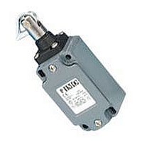
CABLE PULL SWITCH, 12M, 500V
Manufacturer
IMO PRECISION CONTROLS
Datasheet
1.FD978.pdf
(4 pages)
Specifications of FD978
Contact Configuration
DPST-NC
Contact Voltage Ac Max
500V
Cable Span
12m
Length/height, External
131mm
External Width
40mm
Operating Temperature Min
-25°C
Operating Temperature Max
60°C
Lead Free Status / RoHS Status
Lead free / RoHS Compliant


Rope Operated Stop Switches
Notes: a) The terminal screws are M3.5 with rising cable clamps for ease of wiring.
Notes:
Notes:
Notes:
Notes:
680
681
682
Safety contacts
Auxiliary contacts
980
982
Safety contacts
Safety contacts
35 metre models:
Terminal connections
Installation
Note: Simplified
diagram shown
without motor
overload protection
and fuses.
Installation guidelines:
1. The switch bodies should be fixed using M5 screws and
2. The rope should be supported along its length, every 2-3
3. The first and last eyebolts should be a maximum of 300mm
b) The maximum terminal screw torque is 0.8Nm (8kg cm)
c) Fuse protection required against short-circuit in the safety circuit: 10A HRC quick blow max.
d) An earth terminal is provided inside the case.
e) Contact blocks are not removable due to interlocking with the positive break system.
aligned such that the rope is tensioned in the direction of the
plunger travel, not at an angle.
metres, using an eyebolt.
from the switches, to ensure that the rope movement at both
switches is axial, i.e., in the direction of the plunger travel.
FD/FL 683/684/983/984 (35m models)
The rope should be tensioned until the head plunger has
travelled approximately 8mm and then the reset button pulled to
release the mechanism. The force required will be approximately
19.5kg (191N)
f) Terminal numbering in accordance with EN50013
1NO + 1NC
981
2NC
Rope slack
or broken
Correct
tension
Stop
~ 8mm
Start
~ 8mm
Safety switch
Rope pulled
FD or FL681
FD or FL 682
Rope
4. The tensioner should be positioned in the centre of the rope. If
5. The 680/683/684/980/983/984 models can operate up to 35
6. The 874/875 models can operate up to 12 metres.
Note: Simplified
diagram shown
without motor
overload protection
and fuses.
a tensioner is used, 2 thimbles and 2 rope clamps will also be
required.
metres.
874
875
Connections to safety circuits should be made through both sets of
contacts in series. The link 12 – 22 must be added.
12 metre models:
FD/FL 878 (12m models)
The rope should be tensioned until the head plunger has
travelled approximately 4mm. The force required to tension will
be approximately 7.5kg (73.5N)
Correct
tension
~ 4mm
Rope pulled
Stop
Start
Rope slack
Rope
or broken
Safety switch
FD or FL875
Related parts for FD978
Image
Part Number
Description
Manufacturer
Datasheet
Request
R

Part Number:
Description:
SIGNAL RELAY, DPDT, 12VDC, 2A, SMD
Manufacturer:
IMO PRECISION CONTROLS
Datasheet:

Part Number:
Description:
Enclosure
Manufacturer:
IMO PRECISION CONTROLS
Datasheet:

Part Number:
Description:
INVERTER, IMO
Manufacturer:
IMO PRECISION CONTROLS
Datasheet:
Part Number:
Description:
INVERTER, IMO
Manufacturer:
IMO PRECISION CONTROLS
Datasheet:
Part Number:
Description:
INVERTER, IMO
Manufacturer:
IMO PRECISION CONTROLS
Datasheet:
Part Number:
Description:
INVERTER, IMO
Manufacturer:
IMO PRECISION CONTROLS
Datasheet:
Part Number:
Description:
INVERTER, IMO
Manufacturer:
IMO PRECISION CONTROLS
Datasheet:
Part Number:
Description:
INVERTER, IMO
Manufacturer:
IMO PRECISION CONTROLS
Datasheet:

Part Number:
Description:
END PLATE
Manufacturer:
IMO PRECISION CONTROLS
Datasheet:

Part Number:
Description:
END PLATE
Manufacturer:
IMO PRECISION CONTROLS
Datasheet:
Part Number:
Description:
END PLATE , FUSED TERM
Manufacturer:
IMO PRECISION CONTROLS
Datasheet:

Part Number:
Description:
END STOP
Manufacturer:
IMO PRECISION CONTROLS
Datasheet:

Part Number:
Description:
CROSS CONNECTOR
Manufacturer:
IMO PRECISION CONTROLS
Datasheet:
Part Number:
Description:
CROSS CONNECTOR
Manufacturer:
IMO PRECISION CONTROLS
Datasheet:
Part Number:
Description:
Enclosure
Manufacturer:
IMO PRECISION CONTROLS
Datasheet: