K8AB-TH12S AC100-240 Omron, K8AB-TH12S AC100-240 Datasheet - Page 7
K8AB-TH12S AC100-240
Manufacturer Part Number
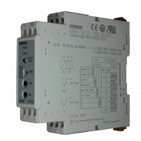
K8AB-TH12S AC100-240
Description
High Temp 0-1700 C Monitor Rel
Manufacturer
Omron
Series
K8ABr
Type
Temperature Monitorr
Datasheets
1.K8AB-TH12S_ACDC24.pdf
(7 pages)
2.K8AB-TH12S_ACDC24.pdf
(8 pages)
3.K8AB-TH12S_AC100-240.pdf
(9 pages)
Specifications of K8AB-TH12S AC100-240
Input Type
RTD, Thermocouple (Multiple)
Controller Type
On/Off
Temperature Range
Selectable, Varies By Input Type
Output Type
Relay
Supply Voltage
100 ~ 240VAC
Size
DIN Rail Module
Coil Voltage
100 VAC to 240 VAC
Contact Termination
Screw
Mounting Style
DIN Rail
Power Consumption
5 VA
Lead Free Status / RoHS Status
Lead free / RoHS Compliant
Features
-
Display Type
-
Communications
-
Lead Free Status / Rohs Status
Lead free / RoHS Compliant
Other names
K8AB-TH12S-AC100-240
K8ABTH12SAC100240
Z2810
K8ABTH12SAC100240
Z2810


Precautions
1. Do not use or store the Temperature Monitoring Relay in the
2. Use and store the Temperature Monitoring Relay within the rated
3. Mount the Temperature Monitoring Relay in the correct direction.
Do not touch the terminals while power is being supplied.
Doing so may occasionally result in minor injury due to
electric shock.
Do not allow pieces of metal, wire clippings, or fine
metallic shavings or filings from installation to enter the
product. Doing so may occasionally result in electric
shock, fire, or malfunction.
Do not use the product where subject to flammable or
explosive gas. Otherwise, minor injury from explosion
may occasionally occur.
Never disassemble, modify, or repair the product or touch
any of the internal parts. Minor electric shock, fire, or
malfunction may occasionally occur.
Loose screws may occasionally result in fire.
Tighten terminal screws to the specified torque of 0.54 to
0.55 N·m.
Set the parameters for the Temperature Monitoring Relay
so that they are appropriate for the system being
monitored. If they are not appropriate, unexpected
operation may occasionally result in equipment damage
or accidents.
Use the following procedure to make the Temperature
Monitoring Relay settings.
• Make settings for the Temperature Monitoring Relay so
• Turn the power supply to the Temperature Monitoring
A malfunction in the Temperature Monitoring Relay may
occasionally make monitoring operations impossible and
prevent alarm outputs, resulting in property damage to
facilities and devices. Conduct periodic maintenance of
the Temperature Monitoring Relay. To maintain safety in
the event of malfunction of the Temperature Monitoring
Relay, take appropriate safety measures, such as
installing a monitoring device on a separate line.
If the output relay is used past its life expectancy, contact
fusing or burning may occasionally occur. Always
consider the application conditions and use the output
relay within its rated load and electrical life expectancy.
The life expectancy of output relays varies considerably
with switching capacity and switching conditions.
that they are appropriate for the system being
monitored.
Relay OFF before setting the switches provided on the
side of the Temperature Monitoring Relay. The settings
made on the switches on the side of the Temperature
Monitoring Relay will be enabled when the power
supply is turned ON.
following locations.
• Places subject to splashing liquid or oil atmosphere
• Places subject to direct radiant heat from heating equipment
• Outdoors or places subject to direct sunlight
• Places subject to dust or corrosive gas (in particular, sulfide gas
• Places subject to intense temperature changes
• Places subject to icing and condensation
• Places subject to vibration and large shocks
temperature and humidity ranges.
Precautions for Safe Use
and ammonia gas)
!CAUTION
Temperature Monitoring Relay
4. Be sure to wire properly with correct polarity of terminals.
5. Do not wire the I/O terminals incorrectly.
6. Use this Temperature Monitoring Relay within the specifications
7. Be sure to make the same settings for the temperature sensor
8. When extending the thermocouple lead wires, always use
9. When extending the lead wires of the platinum resistance
10.Use the specified size of crimped terminals for wiring.
11.Do not wire the terminals that are not used.
12.Use a switch, relay, or other contact so that the power supply
13.Design the system (e.g., control panel) to allow for the 1 second
14.Approximately 30 minutes is required for the correct temperature
15.To avoid inductive noise, keep the wiring for the Temperature
16.Attach a surge suppressor or noise filter to peripheral devices that
17.Microwave interference may affect the Temperature Monitoring
18.A switch or circuit breaker should be provided close to this unit.
19.Do not use paint thinner or similar chemical to clean with. Use
20.Use tools when separating parts for disposal. Contact with the
21.Install the Temperature Monitoring Relay inside another device.
and ratings voltage and load.
type and the Temperature Monitoring Relay input type.
compensating conductors suitable for the type of thermocouple.
thermometer, be sure to use wires that have low resistance (i.e., 5
the same.
voltage reaches the rated voltage within one second. If the
applied voltage is increased gradually, the power supply may not
be reset or malfunctions may occur.
of delay required for the Temperature Monitoring Relay's output to
stabilize after the power is turned ON.
to be detected after turning the power supply to the Temperature
Monitoring Relay ON. Turn the power supply ON at least 30
minutes prior to actually starting monitoring.
Monitoring Relay's terminal block away from power cables
carrying high voltages or large currents. Also, do not wire power
lines together with or parallel to Temperature Monitoring Relay
wiring. Using shielded cables and using separate conduits or
ducts is recommended.
generate noise (in particular, motors, transformers, solenoids,
magnetic coils or other equipment that have an inductance
component).
When a noise filter is used at the power supply, first check the
voltage or current, and attach the noise filter as close as possible
to the Temperature Monitoring Relay.
Allow as much space as possible between the Temperature
Monitoring Relay and devices that generate powerful high
frequencies (high-frequency welders, high-frequency sewing
machines, etc.) or surge.
Relay. Do not use a microwave receiver near the Temperature
Monitoring Relay.
The switch or circuit breaker should be within easy reach of the
operator, and must be marked as a disconnecting means for this
unit.
standard grade alcohol.
sharp internal parts may cause injury.
max. per wire) and keep the resistance of the three lead wires
K8AB-TH
7
Related parts for K8AB-TH12S AC100-240
Image
Part Number
Description
Manufacturer
Datasheet
Request
R

Part Number:
Description:
High Temp 0-1700 C Monitor Rel
Manufacturer:
Omron
Datasheet:

Part Number:
Description:
G6S-2GLow Signal Relay
Manufacturer:
Omron Corporation
Datasheet:
Part Number:
Description:
Compact, Low-cost, SSR Switching 5 to 20 A
Manufacturer:
Omron Corporation
Datasheet:
Part Number:
Description:
Manufacturer:
Omron Corporation
Datasheet:
Part Number:
Description:
Manufacturer:
Omron Corporation
Datasheet:
Part Number:
Description:
Manufacturer:
Omron Corporation
Datasheet:
Part Number:
Description:
Manufacturer:
Omron Corporation
Datasheet:
Part Number:
Description:
Manufacturer:
Omron Corporation
Datasheet:
Part Number:
Description:
Manufacturer:
Omron Corporation
Datasheet: