E5AK-TAA2500AC100/240 Omron, E5AK-TAA2500AC100/240 Datasheet
E5AK-TAA2500AC100/240
Specifications of E5AK-TAA2500AC100/240


Related parts for E5AK-TAA2500AC100/240


E5AK-TAA2500AC100/240 Summary of contents
Page 1
... D Ordering Information When ordering, order control output boards and option boards separately. Example: for a relay control output, order the E53-R output board in addition to the standard Process Controller (E5AK-T/E5EK-T). Also specify the current transformer. J Process Controllers Description Standard model with terminal cover ...
Page 2
... E5AK/E5EK 3/1 E5AK/E5EK 3/1 E5AK/E5EK 3/1 E5AK/E5EK 3/1 Compatible Max. quantity controller E5AK/E5EK 1 E5AK/E5EK 1 E5AK 1 E5EK 1 All 1 E5AK- -T/E5EK- -T Model E53-R E53-S E53-Q E53-Q3 E53-Q4 E53-C3 E53-C3D E53-V34 E53-V35 E53-AK01 E53-AK02 E53-AK03 E53-AKB E53-AKF Model E54-CT1 E54-CT3 E53-COV0809 E53-COV08 Thermo tools ...
Page 3
... UL 1092, CSA22.2 No. 14, CSA22.2 No. 1010-1 C Conforms to EN50081-2, EN50082-2, EN61010-1 (IEC1010- EN50081 2 EN50082 2 EN61010 1 (IEC1010 1) Conforms to VDE0106/part 100 (Finger Protection), when the separately- Conforms to VDE0106/part 100 (Finger Protection), when the separately- ordered terminal cover is mounted. E5AK- -T/E5EK- -T Ramp/Soak Process Controller 3 ...
Page 4
... Time or ramp setting method ±0.2% (±500 ms) of the set value 250 ms 100 ms 20 MΩ min. at 500 VDC ...
Page 5
... Resolution: approx. 2,600 steps E54-CT1 50 amps 1,000 VAC for 1 min 2 50 Hz, 98 m/s (10G) Approx. 11.5 g ---- Single-phase 0.1 to 49.9 A (in units of 0.1 A) (See Note 1) 190 ms (See Note 2) Ramp/Soak Process Controller Specifications E54-CT3 120 amps (See Note 1) Approx Armature: 2; Plug: 2 E5AK- -T/E5EK ...
Page 6
... Current input E5AK- -T/E5EK- -T Pt100 --199.9° to 650.0° --199.9° to 999.9° 0 PLII --200 100 1,700 1,700 to 2,300 1,300 1,300 1,800 --300 0 to ...
Page 7
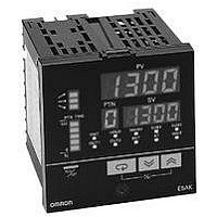
... J E5EK-T Operation indicators Display Key RUN/RST Key RUN/RST Key Switches between RUN and RESET mode. Display 1 Display 2 Up Key/Down Key E5AK- -T/E5EK- -T Ramp/Soak Process Controller Display 1 Displays the process value or parameter code. Display 2 Displays the present SP, manip- ulated variable, or parameter settings. ...
Page 8
... Ramp/Soak Process Controller 13.5 (0.53) 100 (3.94) not be closely mounted (vertically or horizontally). 13.5 (0.53) 100 (3.94) 96 (3.78) (3.58) 22.05 (0.87) 3 (0.12) 3 (0.12) E5AK- -T/E5EK- -T Panel Cutouts 110 (4.33) min. 120 (4.72) min. Panel Cutouts 60 (2.36) min. 112 (4.41) 120 91 (4.72) min. E53-COV08 43 ...
Page 9
... Current Transformers E54-CT1 25 (0.98) 10 (0.39) Unit: mm (inch) E54-CT3 40 (1.57 (1.57) 15 (0.59) 21 (0.83) 2.8 (0.11)dia. 5.8 (0.23) 15 dia. 7.5 (0.30) 10.5 (0.41) 40 (1.57) 30 (1.18) 2.36 (0.09) dia. 30 (1.18) 12 dia. 9 (0.35) Two, M3 (depth (1.18) Ramp/Soak Process Controller E5AK- -T/E5EK ...
Page 10
... To replace the output board, use a flat-blade screwdriver to push up the output board. 10 Ramp/Soak Process Controller J Setting Up the Option Board 1. Insert the option boards into the sockets for options The following diagram shows the relationship between the option boards and mounting positions. E5AK--T E5EK--T E5AK- -T/E5EK ...
Page 11
... Terminal covers are supplied for controllers with -500 in the part number; for non -500 models, order covers separately. Fasten the terminals covers as follows by using the snap pins. Note: Snap pins are provided with the terminal covers. E5AK-T E5EK-T E5AK- -T/E5EK- -T Ramp/Soak Process Controller 11 ...
Page 12
... Solderless terminals are recommended when wiring the Controller. • Tighten the terminal screws using a torque no greater than 0. kgf S cm max. Be careful not to tighten the terminal • screws too tightly. Power Blocks for E5AK-T/EK-T The E5AK/E5EK has independent power supplies for each of the terminal blocks shown below. E5AK ...
Page 13
... Terminal numbers 7 and 8 are for control output 1 (OUT1), and terminal numbers 5 and 6 are for control output 2 (OUT2). The following diagrams show the available output boards and their internal equalizing circuits. With E53-Vjj output boards, approx output for one second after the power is interrupted. E5AK- -T/E5EK- -T Ramp/Soak Process Controller 13 ...
Page 14
... Output specifications are as follows: SPST-NO 250 VAC CT Input/Potentiometer When using the HBA function on the E5AK-TAA2 Controller, connect CT input (CT) to terminal numbers 15 to 17. When monitoring the valve opening on the E5AK-TPRR2 Controller, connect the potentiometer (PTMR) to terminal numbers 15 to 17. Connect each of these inputs as follows: ...
Page 15
... Event input 1 and 2 Event input 3 and EV1 EV3 + + EV2 25 EV4 COM COM -- -- Event input 1 and 2 Event input 3 and 4 ON: 1 kΩ max. OFF: 100 kΩ min. ON: Residual voltage 1.5 V max., OFF: Leakage current 0.1 mA max. Ramp/Soak Process Controller E5AK- -T/E5EK ...
Page 16
... Communications Terminal numbers 18 to 20, 31 and 32 can be used only on Controllers with communications boards (E53-AK01/02/03). For details on wiring, refer to Chapter 6, Using the Communications Function in the E5AK-T/E5EK-T User Manuals (H83 and H85). J E5EK-T WIRING In the following wiring diagrams, the left side of the terminal numbers indicate the inside of the Controller. ...
Page 17
... VDC, permissible load impedance:1 kΩ min., resolution: approx. 2600 VDC, permissible load impedance: 1 kΩ min., resolution: approx. 2600 2 1 Auxiliary output 2 E5AK- -T/E5EK- -T Ramp/Soak Process Controller 17 ...
Page 18
... For details on CT inputs, refer to Appendix, About Current Transformer in the E5AK-T/E5EK-T User’s Manual (H83/H85). For details on the potentiometer, refer to the Instruction Manual for the valve connected to the Controller. The variable resistance range is 100 Ω to 2.5 kΩ. Remote SP Input Connect the input (RSP used as the remote SP to terminal numbers 15 and 16. However, note that the remote SP cannot be used on the E5EK-TPRR2 Controller ...
Page 19
... Terminal numbers can be used only on controllers with 21 communications boards (E53-AK01/02/03). For details on wiring, L refer to Chapter 6, Using the Communications Function in the E5AK-T/E5EK-T User Manuals (H088-E3-1 and H089-E3-1 Operation The alarm outputs of a model with an alarm function may not • turn ON correctly when the model malfunctions. The use of alarm equipment with the Controller is recommended ...
Page 20
... Heater INPUT LOAD -- G3NA E5AK-/E5EK-T: 5 pcs. E5CK-T: 2 pcs VDC Standard model with screw termi- nals E5AK- -T/E5EK- -T Power supply for load Power SSR See the following table. G3NE E5AK-/E5EK-T: 2 pcs. E5CK-T: 1 piece 12 VDC Compact, low-cost model with tab terminals ...
Page 21
... Cancellation; Etc. Orders are not subject to rescheduling or cancellation unless Buyer indemnifies Omron against all related costs or expenses. 10. Force Majeure. Omron shall not be liable for any delay or failure in delivery resulting from causes beyond its control, including earthquakes, fires, floods, strikes or other labor disputes, shortage of labor or materials, accidents to machinery, acts of sabotage, riots, delay in or lack of transportation or the requirements of any government authority ...
Page 22
... OMRON ELECTRONICS LLC • THE AMERICAS HEADQUARTERS Schaumburg, IL USA • 847.843.7900 • 800.556.6766 • www.omron247.com OMRON CANADA, INC. • HEAD OFFICE Toronto, ON, Canada • 416.286.6465 • 866.986.6766 • www.omron.ca OMRON ELETRÔNICA DO BRASIL LTDA • HEAD OFFICE São Paulo, SP, Brasil • 55.11.2101.6300 • www.omron.com.br OMRON ELECTRONICS MEXICO • ...