NM12HBA-M EUCHNER, NM12HBA-M Datasheet - Page 15
NM12HBA-M
Manufacturer Part Number
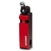
NM12HBA-M
Description
SAFETY SWITCH
Manufacturer
EUCHNER
Datasheet
1.NM12HBA-M.pdf
(31 pages)
Specifications of NM12HBA-M
Actuation Type
Roller Lever
Contact Voltage Ac Max
230V
Contact Voltage Dc Max
24V
Contact Current Ac Max
4A
Contact Current Dc Max
4A
Switch Terminals
Screw
Actuator Type
Roller Lever
Case Material
Thermoplast
Actuator Style
Roller Lever


Safety Switches NM
Technical Data
Convertion of the switch direction
Convertion of the roller levers
Ordering table
Ordering example: NM, switching element ES 12, actuator head HB, approach direction A, cable entry M16x1.5 M
Parameter
Housing material
Environmental protection to IEC 529
Mounting position
Mechanical service life
Ambient temperature
Actuator
Roller material
Approach speed max.
Switching element
Contact elements
Switching principle
Cable entry
Pretravel up to switching point
Rated insulation voltage U
Utilization category to IEC 60 947-5-1
Rated impulse withstand voltage U
Switching voltage min.
Switching current min. at 24 V
Contact material
Connection type
Wire cross section
Short circuit protection (control circuit fuse)
Weight
Design
short
long
Pressing down and turning of
the cam simultaneously
Article
NM01HBA-M
NM11HBA-MC2069
NM02HBA-MC2069
NM11HBA-M
NM02HBA-M
NM12HBA-M
NM03HBA-M
NM12HBA-M
i
imp
Contact elements
1 positively driven NC
1 positively driven NC + 1 NO
2 positively driven NC
1 positively driven NC + 1 NO
2 positively driven NC
2 positively driven NC + 1 NO
3 positively driven NC
Turning of the
operating cam
by means of turning the operating cam
approx. 0.08
1 x M16x1.5
1 NC
ES 01
1 NC
Plunger form Approach direction Cable entry Order No.
AC-15 4 A 230 V / DC-13 4 A 24 V
Dependent action contact element
ES 11
HB
HB
20 x 10
+ 1 NO 2 NC
Reinforced thermoplastic
see switching diagramm
Silver alloy, gold flashed
The roller lever position can be adjusted within a grid
of 10° steps. Additionally the lever can be positioned
with roller to the outside or the inside. After
adjustment of the required approach direction the
roller lever is fixed with a screw.
Switching
to the left
Screw terminal
- 20 to + 80
-90°
Roller lever
0.34 - 1.5
6
optional
switching cycles
Plastic
Value
IP 67
ES 02
250
2.5
60
12
1
4
3 x M16x1.5
approx. 0.1
(standard adjustment)
Switching to the
2 NC
A
A
left / right
ES 12
0°
+ 1 NO 3 NC
Order No. 084 530
M
M
ES 03
to the right
Switching
+90°
084 527
095 369
095 368
084 528
084 529
084 530
084 531
m/min
A gG
mm
Unit
mA
°C
V≅
kV
kg
V
2
15
Related parts for NM12HBA-M
Image
Part Number
Description
Manufacturer
Datasheet
Request
R

Part Number:
Description:
ACTUATOR
Manufacturer:
EUCHNER
Datasheet:

Part Number:
Description:
ACTUATOR
Manufacturer:
EUCHNER
Datasheet:

Part Number:
Description:
ACTUATOR
Manufacturer:
EUCHNER
Datasheet:

Part Number:
Description:
ACTUATOR
Manufacturer:
EUCHNER
Datasheet:

Part Number:
Description:
JOYSTICK SWITCH
Manufacturer:
EUCHNER
Datasheet:

Part Number:
Description:
JOYSTICK SWITCH
Manufacturer:
EUCHNER
Datasheet:

Part Number:
Description:
JOYSTICK SWITCH
Manufacturer:
EUCHNER
Datasheet:

Part Number:
Description:
JOYSTICK SWITCH
Manufacturer:
EUCHNER
Datasheet:

Part Number:
Description:
JOYSTICK SWITCH
Manufacturer:
EUCHNER
Datasheet:


Part Number:
Description:
LIMIT SWITCH, SINGLE
Manufacturer:
EUCHNER
Datasheet:

Part Number:
Description:
SAFETY SWITCH
Manufacturer:
EUCHNER
Datasheet:

Part Number:
Description:
SAFETY SWITCH
Manufacturer:
EUCHNER
Datasheet:

Part Number:
Description:
SAFETY SWITCH
Manufacturer:
EUCHNER
Datasheet:

Part Number:
Description:
SAFETY SWITCH
Manufacturer:
EUCHNER
Datasheet: