HS1E-340KR IDEC, HS1E-340KR Datasheet - Page 2
HS1E-340KR
Manufacturer Part Number
HS1E-340KR
Description
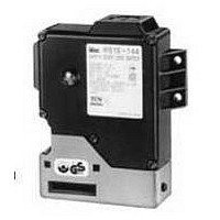
SWITCH, SAFETY INTERLOCK, 2NC, 10A
Manufacturer
IDEC
Datasheet
1.HS1E-340KR.pdf
(11 pages)
Specifications of HS1E-340KR
Contact Configuration
DPDT-NC
Contact Voltage Ac Max
250V
Contact Voltage Dc Max
250V
Contact Current Ac Max
10A
Contact Current Dc Max
6A
Switch Terminals
Screw
Lead Free Status / RoHS Status
Contains lead / RoHS non-compliant


www.idec.com
Conforming to Standards
Applicable Use
Operating Temperature
Storage Temperature
Operating Humidity
Altitude
Rated Insulation Voltage (Ui)
Impulse Withstand Voltage (Uimp)
Insulation Resistance
(measured with 500V DC megger)
Electric Shock Protection
Pollution Degree
Degree of Protection
Vibration
Resistance
Shock Resistance
Actuator Tensile Strength when Locked
Actuator Operating Speed
Positive Opening Travel
Positive Opening Force
Thermal Current (Ith)
Rated Operating Current (Ie)
Contact Gap
Operating Frequency
Mechanical Life
Electrical Life
Conditional Short-Circuit Current
Recommended Short
Circuit Protection
Weight
Rated Operating Voltage
Rated Current
Coil Resistance
Pickup Voltage
DropOut Voltage
Allowable Voltage
Insulation Class
Rated Operating Voltage
Rated Current
Light Source
Lens Color
Safety Products
Operating Extremes
Damage Limits
USA: (800) 262-IDEC or (408) 747-0550, Canada: (888) 317-IDEC
EN1088, IEC60947-5-1, EN60947-5-1(TUV), IISO14119,
GS-ET-19 (BG), UL508, CSA C22.2 No. 14 (c-UL)
IEC60204-1, EN60204-1
–20 to +40˚C (no freezing)
–40 to +80˚C
40 - 85% (no condensation)
2,000m maximum
300V (between LED or solenoid and ground: 60V)
4 kV (between LED or solenoid and ground: 2.5 kV)
Between live and dead metal parts: 100 M minimum
Between live metal part and ground: 100 M minimum
Between live metal parts:
Between terminals of the same pole: 100 M minimum
Class II (according to IEC61140)
3 (IEC60947-5-1)
IP67 (IEC60529)
10 to 55 Hz, minimum (amplitude 0.35 mm)
50 m/sec
1,000 m/sec
1,500N minimum (per GS-ET-19)
1 m/sec maximum
11 mm minimum
20N minimum
Main circuit: 10A, Auxiliary circuit: 3A
Rated operating voltage (Ue)
Main circuit: 1.7 mm min., Auxiliary circuit: 1.2 mm min.
900 operations/hour max.
1,000,000 operations min. (at full rated load)
900 ops/hr (AC-12/250V, 6A)
100,000 operations (rated load)
100A (per IEC60947-5-1)
250V, 10A fuse (Type D01 based on IEC60269-1, 60269-2)
24V DC
235 mA
102 (at 20 C)
20.5V maximum (at 20 C)
2.4 minimum (at 20 C)
26.4V max (continuous)
Class B
24V DC
10 mA
LED lamp
Red or Green (12 mm dia. Lens)
Approx. 500g
AC
DC
AC
DC
2
(approx. 5G)
2
Resistive load (AC12)
Inductive load (AC15)
Resistive load (DC12)
Inductive load (DC13)
Resistive load (AC12)
Inductive load (AC15)
Resistive load (DC12)
Inductive load (DC13)
(approx. 100G)
Specifications
30V
10A
10A
6A
3A
–
–
3A
–
100 M minimum
125V
10A
5A
–
0.9A
3A
–
–
0.9A
250V
6A
3A
–
–
3A
3A
–
–
HS1E - 2 4 4 K R - R
Ordering Information
Circuit Diagram No.
Blank:
1:
2:
3:
Main Circuit
1NC+1NC
1NC+1NC
1NC+1NC
1NC+1NC
Indicator Rated Voltage:
4 (24V DC)
0 (without indicator)
Manual Unlock Key:
K
Blank (without key)
HS1E Series
Indicator Color:
1NO
1NC+1NC
1NO/1NO
(with key)
Auxiliary Circuit
1NC
R (Red)
G (Green)
B1-31
B1
Related parts for HS1E-340KR
Image
Part Number
Description
Manufacturer
Datasheet
Request
R

Part Number:
Description:
HS1E-140KRP Solenoid Sfty Swtch 2NC/1NO W/unlock PG13.5
Manufacturer:
IDEC
Part Number:
Description:
HS1E-144KR-R Solenoid Sfty Swtch 2NC/1NO W/man&ind G1-2
Manufacturer:
IDEC
Part Number:
Description:
HS1E-244R-G Solenoid Sfty Swtch 2NC/2NC W/ind G1/2
Manufacturer:
IDEC
Part Number:
Description:
HS1E-340KRP Solenoid Sfty Swtch 2NC/1NC W/unlock PG13.5
Manufacturer:
IDEC
Part Number:
Description:
HS1E-44KR-R Solenoid Sfty Swtch 2NC/2NO W/man&ind G1/2
Manufacturer:
IDEC
Part Number:
Description:
Hs1e Series Full Size Interlock Switch With Locking Solenoid
Manufacturer:
IDEC Corporation
Datasheet:
Part Number:
Description:
Hs1e Series Full Size Solenoid Locking Switches
Manufacturer:
IDEC Corporation
Datasheet:

Part Number:
Description:
SWITCH, SAFETY INTERLOCK, 2NC, 10A
Manufacturer:
IDEC
Datasheet:
Part Number:
Description:
Switch, SAFETY, WITHOUT INDICATOR, WITHOUT KEY, 2NC/1NO
Manufacturer:
IDEC Corporation
Datasheet:

Part Number:
Description:
IC LN-DRVR ARINC 429 16-SBDIP
Manufacturer:
Intersil
Datasheet:
Part Number:
Description:
IC,LINE TRANSCEIVER,CMOS,1 DRIVER,2 RCVR,DIP,40PIN,CERAMIC
Manufacturer:
Intersil
Datasheet:
Part Number:
Description:
Manufacturer:
Intersil
Datasheet:
Part Number:
Description:
Manufacturer:
Intersil
Datasheet:

Part Number:
Description:
ARINC 429 Bus Interface Line Driver Circuit
Manufacturer:
Intersil Corporation