SI-HG63FQDR BANNER ENGINEERING, SI-HG63FQDR Datasheet
SI-HG63FQDR
Manufacturer Part Number
SI-HG63FQDR
Description
SWITCH, SAFETY INTERLOCK, 3NC/3NO, 3A
Manufacturer
BANNER ENGINEERING
Type
Interlockr
Specifications of SI-HG63FQDR
Contact Voltage Ac Max
230V
Contact Voltage Dc Max
24V
Contact Current Ac Max
3A
Contact Current Dc Max
1A
Switch Terminals
Quick Connect
Actuator Type
Flexible
Contact Form
1 NO, 2 NC
Current, Rating
3/1 AAC/ADC
Function
Safety
Ip Rating
IP67
Number Of Poles
3
Number Of Positions
2
Termination
Quick Connect
Voltage, Rating
230/24 VAC/VDC


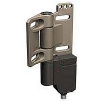
*NOTE: Terminals 33 and 34 are non-safety.
SI-HG63FQDR
SI-HG63FQDL
SI-HG63FQDRR
Model SI-HG63FQDR
Model
shown
QD Connection
Housing Style/
mounted on right
With switch body
mounted on right
Right-Angle QD
mounted on left
With QD facing
down, switch is
With QD facing
down, switch is
down, switch is
side of hinge
side of hinge
side of hinge
Inline QD
Inline QD
rd/bu
gn
rd
33
21
11
rd/bu
Contact Configuration*
gn
rd
(Gate Closed State)
• Safety switch is integrated into a highly robust PBT housing and screwed onto the
• Safety switching point is repositionable.
• Right-hinge, left-hinge, and right-angle hinge models available; switches can also be
• A non-switching blank hinge is also available (see page 7).
• Switch components are protected from mechanical impact, for superior performance
• Hinge operates to a full 270° range of motion; safety switching point (guard-closed
• Hinge can support an axial and radial load of 1200 N (120 Kg).
• When properly interfaced or used with an appropriate controller, two SI-HG63
• Typical applications include:
33
21
11
34
22
12
Hinge Wing Safety Interlock Switches
SI-HG63 Series Safety Interlock Switches Attached to a Load-Bearing Hinge
fine-cast stainless steel hinge.
converted to operate from the opposite side.
to actuator-activated safety switches; rated IEC IP67.
position) is adjustable over the full 0–270°operating range.
switches on an individual gate or guard can achieve safety category 4, per
ISO 13849-1 (EN 954-1).
– Hinged covers and guards to machines
– Hinged doors and gates in safety fencing systems
– Modular aluminum framing
rd/bk
rd/ye
rd/wh
34
22
12
rd/bk
rd/ye
rd/wh
Models
10/06
Contact Configuration*
rd/bu
gn
rd
(Gate Open State)
33
21
11
rd/bu
gn
rd
33
21
11
34
22
12
Features
rd/bk
rd/ye
rd/wh
34
22
12
rd/bk
rd/ye
rd/wh
Contacts:
6°
3°
3°
6°
Open
Switching
Diagram
Closed
9°
9°
Transition
Related parts for SI-HG63FQDR
Image
Part Number
Description
Manufacturer
Datasheet
Request
R

Part Number:
Description:
SI-HG63-W-10 ACCESSORY CODING RING-10 PACK
Manufacturer:
BANNER ENGINEERING
Part Number:
Description:
Replacement Accessory Kit
Manufacturer:
BANNER ENGINEERING
Datasheet:

Part Number:
Description:
PCB FUSE CARRIER AUTO TYPE 15A
Manufacturer:
Phoenix Contact
Datasheet:
Part Number:
Description:
PCB FUSE CARRIER AUTO TYPE 30A
Manufacturer:
Phoenix Contact
Datasheet:

Part Number:
Description:
Photoelectric Sensor
Manufacturer:
BANNER ENGINEERING
Datasheet:

Part Number:
Description:
Photoelectric Sensor
Manufacturer:
BANNER ENGINEERING
Datasheet:
Part Number:
Description:
LEDIR70XD4-XM-81039 MAX INTENS STROBE ONLY NO BANNER MARKS
Manufacturer:
BANNER ENGINEERING
Part Number:
Description:
M18SP6DL-72225 LABELED MOELLER NO BANNER MARKINGS BULK PACK
Manufacturer:
BANNER ENGINEERING
Part Number:
Description:
Photoelectric Sensor
Manufacturer:
BANNER ENGINEERING
Datasheet:

Part Number:
Description:
Programmable Indicator Light
Manufacturer:
BANNER ENGINEERING
Datasheet:
Part Number:
Description:
INDICATOR LED PANEL 50MM GRN/RED/YEL 30V
Manufacturer:
BANNER ENGINEERING
Datasheet:
Part Number:
Description:
Programmable Indicator Light
Manufacturer:
BANNER ENGINEERING
Datasheet:
SI-HG63FQDR Summary of contents
Page 1
... Model SI-HG63FQDR shown Housing Style/ Model QD Connection Inline QD With QD facing SI-HG63FQDR down, switch is mounted on right side of hinge Inline QD rd/bu With QD facing SI-HG63FQDL gn down, switch is mounted on left rd side of hinge Right-Angle QD With switch body SI-HG63FQDRR down, switch is mounted on right side of hinge *NOTE: Terminals 33 and 34 are non-safety. ...
Page 2
... Dimensions for model SI-HG63FQDL are a mirror image. M12X1 Specifications N.O. Contact: ± 9 ° Dimensions Model SI-HG63FQDRR 19.5 mm (0.77") 33.0 mm (1.30" (0.71") 63.0 mm (2.48") 45.0 mm (1.77") 147.0 mm (5.79") SI-HG63 Series 4.0 mm 20.0 mm (0.79") (0.16") M12X1 13.5 mm (0.53" ...