ATV12HU22M3 SQUARE D, ATV12HU22M3 Datasheet - Page 32
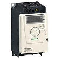
ATV12HU22M3
Manufacturer Part Number
ATV12HU22M3
Description
AC Drive
Manufacturer
SQUARE D
Specifications of ATV12HU22M3
No. Of Phases
Three
Power Rating
2.2kW
Output Voltage Max
230V
Output Current
10A
Supply Voltage Max
230V
Frequency Range
0.5 To 400Hz
Rohs Compliant
Yes
Lead Free Status / RoHS Status
Lead free / RoHS Compliant


10
1
2
3
4
5
6
7
8
9
HSP
HSP
Functions
HSP: High speed
t1 = k1 x t2 (k1: fixed rounding coefficient)
t2: Ramp time set
S ramps
HSP: High speed
t1 = k2 x t2 (k2: fixed rounding coefficient)
t2: Ramp time set
U ramps
f (Hz)
1
2
3
Stop types
Introduction:
page 8
f (Hz)
f (Hz)
0
Fast stop
Stop on deceleration ramp
Freewheel stop
0
30
t1
t2
t1
t2
HSP
t
HSP
t
(continued)
f (Hz)
f (Hz)
0
0
1
Specifications:
page 10
t2
t1
t1
2
t2
3
t
t
t
Altivar
variable speed drives
Ramp time switching
This function is used to switch two acceleration and deceleration ramp times,
which can be set separately.
Enabled by means of 1 assignable logic input.
It is suitable for machines with fast speed correction in steady state and high-speed
lathes with acceleration and deceleration limiting above certain speeds.
Acceleration and deceleration ramp profiles
This function can be used to gradually increase the output frequency starting from a
speed reference, following a linear profile or a preset profile.
v S ramps
The use of S ramps is dedicated to applications involving handling, packaging and
passenger transport; this method takes up mechanical backlash and eliminates jolts,
and also limits “non-following” of speed during rapid transient operation of high-
inertia machines.
v U ramps
The use of U ramps is dedicated to pump applications such as an installation with
centrifugal pump and non-return valve; this method enables valve closing to be
controlled more accurately.
Selecting “linear”, “S”, or “U” profiles will affect both the acceleration and
deceleration ramps.
Automatic adaptation of deceleration ramp
This function is used to increase the deceleration time automatically if the initial
setting is too low when the load inertia is taken into account. It prevents the drive
locking on an “overvoltage on deceleration” fault.
If a braking unit is connected to the drive, this function must be disabled.
Stop types
This is used to define the drive stop mode.
There are three stop types:
v Freewheel stop: When the drive is locked, the motor stops in freewheel mode
depending on the application; the motor power supply is cut.
v Stop on deceleration ramp: The motor stops according to the deceleration ramp
time which can be fixed or adaptable (see the “Automatic adaptation of deceleration
ramp” function).
v Fast stop: Braked stop with an acceptable deceleration ramp time (divided by a
coefficient which can be set between 1 and 10) for the drive/motor unit without
locking in the event of an “overvoltage on deceleration” fault.
Factory-set configuration: Stop on 3 s deceleration ramp with automatic adaptation.
References:
page 14
®
12
Dimensions:
page 18
Connections:
page 22
Related parts for ATV12HU22M3
Image
Part Number
Description
Manufacturer
Datasheet
Request
R


Part Number:
Description:
Pushbutton, Non-Illum'd Red "STOP", Momentary, 1NO-1NC, Square 30mm, 10A, 600V
Manufacturer:
SQUARE D
Datasheet:
Part Number:
Description:
CB ACCESSORY, UNDERVOLTAGE TRIP 48V DC
Manufacturer:
SQUARE D
Datasheet:
Part Number:
Description:
CB ACCESSORY, TRIP UNIT
Manufacturer:
SQUARE D
Datasheet: