XTAE007B10TD004 EATON CUTLER HAMMER, XTAE007B10TD004 Datasheet - Page 111
XTAE007B10TD004
Manufacturer Part Number
XTAE007B10TD004
Description
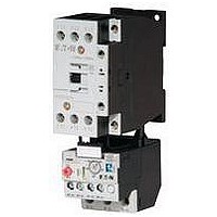
IEC Non-Reversing Starter
Manufacturer
EATON CUTLER HAMMER
Datasheet
1.XTAE007B10A001.pdf
(240 pages)
Specifications of XTAE007B10TD004
No. Of Phases
Single Or Three
Power Rating
3.5kW
Current Rating
7A
Operating Temperature Range
-25°C To +50°C
Mounting Type
DIN Rail
Overload Adjustment Current Max
4A
Overload Adjustment Current Min
2.4A
Supply Voltage Max
24VDC
Frame Size
Standard


Wiring Diagrams
7–150A XTCR Reversing Contactors
Control Circuit—7–32A
K1M
Star-Delta (Wye-Delta) Starters
Power Circuit—12–385A AC-3
K1M
Control Circuit—12–55A AC-3
(–)N
Control Circuit—70–1700A AC-3
S11
(–)N
0.58 x ln
K1M
S11
I
0
0
II
I
I
0
K1M
K2M
K1M
K1M
K1M
22
14
13
21
13
14
22
22
13
14
21
21
21
22
54
53
21
A1
22
2
A2
1
N
N
13
14
44
43
A1
K1M
A2
K3M
3
4
13
14
54
53
A1
A2
K1M
K3M
K2M
5
6
K2M
K1M
F1
K5M
A
L1 L2 L3
13
14
0.58 x l n
U1
V1
W1
K5M
54
53
K5M
54
53
K1T
21
A1
22
A2
K1T
21
13
14
M1
14
13
22
3~
M1
54
53
1
2
B
3
4
1 x l
5
6
W2
U2
A1
A2
V2
A1
A2
K3M
K3M
C
K3M
K5M
n
K5M
K1
K1
Y
Y
17
18
22
21
A1
A2
18
22
21
1
2
17
A1
A2
3 5
4
K5M
K1
K5M
K3M
K1
6
K3M
17
28
22
21
A2
A1
17
28
22
21
A2
A1
Control Circuit—40–170A
(-)N
K1M
K1M
II
0
I
K2M
13
22
22
14
21
21
14
13
21
A1
22
A2
Volume 5—Motor Control and Protection CA08100006E—May 2011 www.eaton.com
K2M
K2M
K1M 22
14
13
21
A1
A2
21
13
14
22
IEC Contactors and Starters
Power Circuit—7–150A
with Mechanical Interlock
80–150A on Mounting Plate
K1M
XTCC Contactors for Three-Phase Capacitors
Power Circuit—11–85 kVar
In the case of group
compensation, multi-stage
capacitor banks are
connected to the mains, as
required. In the process,
transient currents of up to
180 x I
the capacitors. The capacitors
are pre-charged via the early-
make auxiliary contacts and
the fitted wire resistors,
thereby reducing the inrush
current. The main contacts
then close after a time lag
and carry the uninterrupted
current. The contactors for
capacitors are weld-resistant
with inrush current peaks up
to 180 x 1 I
special contacts. For
switching reactive-power
compensation equipment
with chokes, observe
design notes.
A1
A2
M1
R11
1 3 5
2
e
U V W
4
3
M
can flow between
L1 L2 L3
6
1
2
R11
K2M
C1
e
3
4
due to their
5
6
1 3 5
2
R11
4
6
XT IEC Power Control
For switching of power factor
connection with reactors,
please observe engineering
notes, Page V5-T27-66. Use
of the contactors XTCE
without series resistor for
centralized power factor
correction—when using
contactors for group
compensation, a minimum
inductance of approximately
6 μH per capacitor must be
available to limit the high
inrush current peaks. This
corresponds to an air-cored
coil with 5 windings and a coil
diameter of approximately
140 mm diameter. The
conductor cross-section must
be selected according to the
rated current per phase.
27.1
V5-T27-111
Related parts for XTAE007B10TD004
Image
Part Number
Description
Manufacturer
Datasheet
Request
R

Part Number:
Description:
SUB FEED LUG BLOCK 150A CUTLER HAMMER TYPE BR LOADCENTER
Manufacturer:
EATON CUTLER HAMMER
Part Number:
Description:
Handle Tie Bar For (2) - 1 Pole Type BR Breakers
Manufacturer:
EATON CUTLER HAMMER
Part Number:
Description:
Type CL Breaker 25A/1Pole 120/240V 10K-Classified 1" Ckt Bkr
Manufacturer:
EATON CUTLER HAMMER