PAXCDC40 Red Lion Controls, PAXCDC40 Datasheet - Page 12
PAXCDC40
Manufacturer Part Number
PAXCDC40
Description
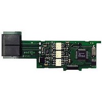
Modbus Communications Network Interface Card
Manufacturer
Red Lion Controls
Specifications of PAXCDC40
Accessory Type
Modbus Communications Network Interface Card
Brand/series
PAX Series
Card Type
Extended Modbus Communications Card
Data Rate
7⁄8 Bits
Standards
cULus Listed, CSA Certified and CE Marked
Voltage, Working
50 V
Pax Label Kit
189 Different Engineering Units, Labels Inserted Inside the Unit
For Use With
Red Lion PAX Digital Input Panel Meters
Lead Free Status / RoHS Status
Lead free / RoHS Compliant


PROGRAMMING MODE ENTRY (PAR KEY)
programmed in this mode. The Programming Mode is entered by pressing the
PAR
hardware lock.
permits only certain parameters to be viewed and/or modified. All meter
functions continue to operate except the front panel keys change to Programming
Mode Operations. Quick Programming Mode is configured in Module 3. Full
Programming Mode permits all parameters to be viewed and modified. In this
mode, incoming counts may not be recognized correctly, the front panel keys
change to Programming Mode Operations and certain user input functions are
disabled. Throughout this document, Programming Mode (without Quick in
front) always refers to “Full” Programming.
MODULE ENTRY (ARROW & PAR KEYS)
together parameters that are related in function. The display will alternate between
the desired module. The displayed module is entered by pressing the
MODULE MENU (PAR KEY)
module discussion). The
to be changed, without changing the programming of preceding parameters.
After completing a module, the display will return to
continue by accessing additional modules.
SELECTION / VALUE ENTRY (ARROW & PAR KEYS)
the selections/value for that parameter. The arrow keys (
to move through the selections/values for that parameter. Pressing the
stores and activates the displayed selection/value. This also advances the meter
to the next parameter.
changed. Once a digit is selected, the arrow keys are used to increment or
decrement that digit to the desired number.
6.0 P
Shaded areas represent program access that is model dependent.
6.1 MODULE 1 - C
The meter normally operates in the Display Mode. No parameters can be
Two types of programming modes are available. Quick Programming Mode
The Programming Menu is organized into nine modules. These modules group
Each module has a separate module menu (which is shown at the start of each
For each parameter, the display alternates between the present parameter and
For numeric values, the
and the present module. The arrow keys (
key. If it is not accessible then it is locked by either a security code, or a
Module 1 is the programming for Counter A, Counter B and the Prescaler Output. Counter B parameters follow the Prescaler parameters. For
maximum input frequency, the counters should be set to mode NONE and the Prescaler to NO when they are not in use. When set to NONE
or NO, the remaining related parameters are not accessible. A corresponding annunciator indicates the counter being shown in the Display
Mode. An Exchange Parameter Lists feature for scale factors and count load values is explained in Module 2.
x = Counter A or Counter B
ROGRAMMING THE
PAR
RST
key is pressed to advance to a particular parameter
PAXC & I
key may be used to select a specific digit to be
F1
and
OUNT
F1
F2
. Programming may
) are used to select
and
PROGRAMMING MENU
F2
PARAMETER MENU
A & B I
PAR
) are used
PAR
OVERVIEW
key.
key,
M
12
ETER
PROGRAMMING MODE EXIT (DSP KEY or at
in the Programming Mode) or the
commit any stored parameter changes to memory and return the meter to the
Display Mode. If a parameter was just changed, the
to store the change before pressing the
returning to the Display Mode, verify recent parameter changes.)
PROGRAMMING TIPS
If lost or confused while programming, press the
programming is complete, it is recommended to record the parameter
programming on the Parameter User Chart and lock out parameter programming
with a user input or lock-out code.
FACTORY SETTINGS
starting point for programming problems. Most parameters can be left at their
Factory Settings without affecting basic start-up. These parameters are
identified throughout the module explanations.
ALTERNATING SELECTION DISPLAY
appear. This is used to illustrate the display alternating between the parameter
on top and the parameter’s Factory Setting on the bottom. In most cases,
selections and values for the parameter will be listed on the right.
NPUT
The Programming Mode is exited by pressing the
It is recommended to start with Module 1 for counting and Module 4 for rate.
Factory Settings may be completely restored in Module 9. This is a good
In the explanation of the modules, the following dual display with arrows will
Indicates Program Mode Alternating Display
Parameter
P
ARAMETERS
Factory Settings are shown.
PAR
key (with
DSP
Selection/Value
key. (If power loss occurs before
(
DSP
PAR
DSP
key and start over. When
key should be pressed
displayed). This will
key (from anywhere
)
PAR KEY)
Related parts for PAXCDC40
Image
Part Number
Description
Manufacturer
Datasheet
Request
R

Part Number:
Description:
Counter
Manufacturer:
Red Lion Controls
Datasheet:
Part Number:
Description:
Miniature Length Sensor
Manufacturer:
Red Lion Controls
Datasheet:
Part Number:
Description:
Model Lsc - Single Channel Output Length Sensor
Manufacturer:
Red Lion Controls
Datasheet: