DMS-30-CP Murata Power Solutions Inc, DMS-30-CP Datasheet - Page 3
DMS-30-CP
Manufacturer Part Number
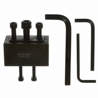
DMS-30-CP
Description
PANEL CUTOUT PUNCH FOR DMS-30/40
Manufacturer
Murata Power Solutions Inc
Type
Panel Punchr
Specifications of DMS-30-CP
Rohs Compliant
NA
Equipment Type
Panel Punch
Lead Free Status / RoHS Status
Lead free by exemption / RoHS compliant by exemption
Lead Free Status / RoHS Status
Lead free by exemption / RoHS compliant by exemption
Other names
811-1122


3. Low Battery Annunciator: The “BAT” annunciator in the upper left-hand
4. HOLD/BACKLIGHT (Pin 9) Function: For non-backlit models, connecting
5. ANALOG COMMON (Pin 10): This pin is connected to an internal, low-
6. REFERENCE IN/OUT (Pin 7): This pin accesses the meter’s internal refer-
7. Gain Adjust: There is a gain-adjust potentiometer on the back of each
corner of the display turns on when the supply voltage for 5V-powered
models falls below the approximate range of 2.7V to 3.7V, or when the
supply voltage for 9V-powered models falls below the approximate range of
5.4 to 7.2V. This function can not be disabled.
Please note, the “BAT” annunciator is a convenience feature only. The supply
voltage ranges specifi ed previously in the ‘Performance/Functional Specifi ca-
tions’ section of this data sheet must be maintained at all times in order to
ensure the DMS-40LCD meets its accuracy and stability specifi cations.
pin 9 (HOLD/BACKLIGHT) to pin 3 (5V RETURN/
–BATTERY) will hold (continuously display) the last reading.
If not used, pin 9 should be left open for these models.
For backlit models, grounding pin 9 (i.e. connecting it to pin 3) turns on the
backlighting LED’s. 9V-powered backlit models function with supply voltages
up to +14V, however, activating the backlight with voltages greater than
9.2V can damage the meter. Therefore, a 1/4 Watt series resistor must be
installed between pins 3 and 9 in these situations. The value of the series
resistor is determined using the following formula:
In any backlit application, including those with supply voltages
by the meter) can be reduced by installing a 1/4 Watt resistor between pins 3
and 9. The brightness of the backlight will be reduced proportionately.
noise, “relative” ground. It is used in certain “fl oating” measurements as
described in the Applications section of this data sheet and Ap Note 3 of the
DATEL Panel Meter Catalog. Pin 10 should not be connected to pin 3 (5V
RETURN/–BATTERY) or to your system’s analog ground.
ence and is used during the factory calibration procedure. Pin 7 should be
left open in most common applications. It can be used in certain “ratiometric”
applications in which it is desireable for the meter’s reference to track an
external reference. See the Applications section of the DATEL Panel Meter
Catalog for more details.
meter. It has approximately ±150 counts of adjustment range. Since
these devices essentially have no zero/offset errors, a gain adjustment is
effectively an overall accuracy adjustment. Though they may be performed
at any point (except zero), accuracy adjustments are most effective when
performed with higher level input signals.
< 9.2V, the current drawn by the backlight (and therefore the current drawn
R
R
R
Example: If +BATTERY (pin 1 with respect to pin 3) is +12.6V,
Series
Series
Series
= 97 Ohms
=
=
+BATTERY – 9.2V
+12.6 – 9.2V
0.035
0.035
Ohms
Ohms
www.murata-ps.com/dpm
8. Soldering Methods: All models in the DMS-40LCD Series easily withstand
9. Suggested Mating Connectors:
APPLICATIONS
DMS-40LCD meters are available in either 5V-powered or 9V-powered models.
9V devices operate directly from 7.5V to 14V supplies (usually batteries) without
the need for external voltage regulators. 9V devices, however, can not be used
to measure voltages referenced to the negative battery terminal (pin 3) because
the minus input to the meter (pin 12, (–) INPUT LO) must always be at least
1.5V above pin 3. 9V-powered meters can only be used to make differential and
not single-ended measurements.
5V-powered devices operate from any well-regulated +5V supply and will ac-
curately measure voltages both above and below pin 3 (5V RETURN) in either
single-ended or differential confi gurations.
1. Single-Ended Input Confi gurations: True single-ended measurements
most common wave soldering operations. We recommend, however, you
evaluate the effects your particular soldering techniques may have on the
meter’s plastic case and high-precision electrical performance. We recom-
mend the use of no-clean solders.
Panel mounted:
Connector housing
Terminal type
Crimping tool
Wire size
Insulation diameter
Stripping length
Board mounted:
Socket
can only be made with 5V-powered meters. The circuit of Figure 2 avoids
problems normally associated with ground loop currents. Separate ground
runs should be used for 5V RETURN (pin 3) and (–) INPUT LO (pin 12).
4½ Digit, LCD Display Digital Panel Voltmeters
+
–
120 VAC
V
IN
AC to DC Converter
Figure 2. Single-Ended Input Confi guration
(–) IN LO
(+) IN HI
DMS-40LCD Series
11
12
(5V-Powered Models)
+5V SUP
DATEL P/N 4320-01069-0
DATEL P/N 4400-01032-0
DATEL P/N 39-2099000
22 to 26 AWG
0.062” (1.57mm) maximum
0.100 to 0.125” (2.54 to 3.17mm)
DATEL P/N 4320-01074-0
04/05/11 MPM_DMS40LCD.C04 Page 3 of 6
1
RANGE
DMS-40LCD-0/1-5
2
email: sales@murata-ps.com
6
DP1
3
5V RET
Related parts for DMS-30-CP
Image
Part Number
Description
Manufacturer
Datasheet
Request
R

Part Number:
Description:
DMS-30 AC-Power Appl. Board
Manufacturer:
Murata Power Solutions Inc
Datasheet:

Part Number:
Description:
DMS-30 Temp. Appl. Board Cel
Manufacturer:
Murata Power Solutions Inc
Datasheet:
Part Number:
Description:
DMS-30 Temp. Appl. Board Farn
Manufacturer:
Murata Power Solutions Inc
Datasheet:

Part Number:
Description:
2-Wire Metr -30-264Vdc Red LED
Manufacturer:
Murata Power Solutions Inc
Datasheet:

Part Number:
Description:
PMount Bezel & Gasket For DMS-30/40
Manufacturer:
Murata Power Solutions Inc
Datasheet:

Part Number:
Description:
Voltage Meter
Manufacturer:
Murata Power Solutions Inc
Datasheet:

Part Number:
Description:
DMS-30 Panel Mount Adapter
Manufacturer:
Murata Power Solutions Inc
Datasheet:
Part Number:
Description:
DMS-30 Red Plastic Case
Manufacturer:
Murata Power Solutions Inc
Datasheet:
Part Number:
Description:
DMS-EB Blank PC-Board DMS-30
Manufacturer:
Murata Power Solutions Inc
Datasheet:

Part Number:
Description:
4-20mA LCD Loop-Power 3.5 Dig
Manufacturer:
Murata Power Solutions Inc
Datasheet:
Part Number:
Description:
Digital Panel Meters DMS-20 BezelAssembly Panel mount
Manufacturer:
Murata Power Solutions Inc
Datasheet:

Part Number:
Description:
DPM LED MINI 2VDC 3.5DIG LP RED
Manufacturer:
Murata Power Solutions Inc
Datasheet:

Part Number:
Description:
DPM LED 2VDC 4.5DIGIT GREEN
Manufacturer:
Murata Power Solutions Inc
Datasheet:

Part Number:
Description:
DPM LED 2VDC 3.5DIGIT LP RED
Manufacturer:
Murata Power Solutions Inc
Datasheet:

Part Number:
Description:
Transformers 5Vin 5Vout 200mA 4000Vdc 1:1.33 turn
Manufacturer:
Murata Power Solutions Inc
Datasheet: