RTE-B2AF20 IDEC, RTE-B2AF20 Datasheet - Page 4
RTE-B2AF20
Manufacturer Part Number
RTE-B2AF20
Description
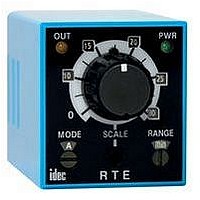
Electromechanical Multifunction Timer
Manufacturer
IDEC
Type
Multi-Moder
Datasheet
1.RTE-B1AD24.pdf
(7 pages)
Specifications of RTE-B2AF20
Time Range
0.1 Sec. To 600 Hr.
Mounting Type
11-blade
Time Range Min
0.1s
Supply Voltage Min
100VAC
Peak Reflow Compatible (260 C)
No
Supply Voltage
240VAC
Leaded Process Compatible
No
Supply Voltage Max
240VAC


DIN Rail Mount Socket
Types
Installation of Hold-Down Springs
Special expertise is required to use Electronic Timers.
• All Electronic Timers are manufactured under IDEC's rigorous qual-
• Install the Electronic Timer according to instructions described in
• Make sure that the operating conditions are as described in the spec-
• In these directions, safety precautions are categorized in order of
Warnings
Warning notices are used to emphasize that improper operation may
cause severe personal injury or death.
• Turn power off to the Electronic timer before starting installation,
www.idec.com
Socket SR2P-06
ity control system, but users must add a backup or fail safe provision
to the control system when using the Electronic Timer in applica-
tions where heavy damage or personal injury may occur should the
Electronic Timer fail.
this catalog.
ifications. If you are uncertain about the specifications, contact
IDEC in advance.
importance under Warning and Caution.
removal, wiring, maintenance, and inspection on the Electronic
Timer.
R T E - P 1 A F 2 0
Connection type
P: Pin
B: Blade
Insert the springs into the outer
slots with the projections
facing inside.
Operation Mode
1: No Control Signal
Hold-down Spring (sold separately)
SFA-202 (use two springs)
A: ON-Delay 1
B: Interval
C: Cycle 1
D: Cycle 3
Mounting A
Timers
Power Voltage
AF20: 100 to 240V AC(50/60Hz)
AD24: 24V AC(50/60Hz)/24V DC
D12: 12V DC
2: Control Signal
A: ON-Delay 2
B: Cycle 2
C: Cycle 4
D: Signal ON/OFF-Delay
E: Signal OFF-Delay
F: One-Shot
USA: (800) 262-IDEC or (408) 747-0550, Canada: (888) 317-IDEC
10A
Socket SR3P-05
7A
Ambient Temperature
Mounting A
Derating Curve
Temperature Derating Curves
50ºC 65ºC
Insert the springs
into the slots.
Hold-down Spring (sold separately)
SFA-203 (use two springs)
Safety Precautions
Instructions
• Failure to turn power off may cause electrical shocks or fire hazard.
• Do not use the Electronic Timer for an emergency stop circuit or
Caution
Caution notices are used where inattention might cause personal
injury or damage to equipment.
• The Electronic Timer is designed for installation in equipment. Do
• Install the Electronic Timer in environments described in the specifi-
• Use an IEC60127-approved fuse and circuit breaker on the power
• Do not disassemble, repair, or modify the Electronic Timer.
• When disposing of the Electronic Timer, do so as industrial waste.
Switch Settings
interlocking circuit. If the Electronic Timer should fail, a machine
malfunction, breakdown, or accident may occur.
not install the Electronic Timer outside equipment.
cations. If the Electronic Timer is used in places where it will be
subjected to high-temperature, high-humidity, condensation, corro-
sive gases, excessive vibrations, or excessive shocks, then electrical
shocks, fire hazard, or malfunction could result.
and output line outside the Electronic Timer.
1
Mounting B
1
2
3
Operation Mode
Selector
Scale Selector
Time Range
Selector
3
2
1. Turn the selectors securely using a flat
2. Since changing the setting during timer
screwdriver 4mm wide (maximum).
Note that incorrect setting may cause
malfunction. Do not turn the selectors
beyond their limits.
operation may cause malfunction, turn
power off before changing.
7A
5A
Ambient Temperature
Mounting B
Derating Curve
50ºC 65ºC
RTE Series
G-11
G
Related parts for RTE-B2AF20
Image
Part Number
Description
Manufacturer
Datasheet
Request
R

Part Number:
Description:
Relay; SSR; Timing; Multi-Function; DPDT; Cur-Rtg 10A; Ctrl-V 24V; Vol-Rtg 240/30AC/DC
Manufacturer:
IDEC Corporation
Datasheet:
Part Number:
Description:
Relay; SSR; Timing; Multi-Function; DPDT; Cur-Rtg 10A; Ctrl-V 24V; Vol-Rtg 240/30AC/DC
Manufacturer:
IDEC Corporation
Datasheet:
Part Number:
Description:
Relay; SSR; Timing; Multi-Function; DPDT; Cur-Rtg 10A; Ctrl-V 12DC; Vol-Rtg 240/30AC/DC
Manufacturer:
IDEC Corporation
Datasheet:
Part Number:
Description:
Relay; SSR; Timing; Multi-Function; DPDT; Cur-Rtg 10A; Ctrl-V 12DC; Vol-Rtg 240/30AC/DC
Manufacturer:
IDEC Corporation
Datasheet:

Part Number:
Description:
PCIMCIA CARD MIDAS FOR OEM
Manufacturer:
Renesas Electronics America
Part Number:
Description:
V850E MA1 EVAL GHS TOOLS DIPSW
Manufacturer:
Renesas Electronics America
Datasheet:
Part Number:
Description:
MIDAS LABS N-WIRE ICE V850E MA1
Manufacturer:
Renesas Electronics America
Datasheet:

Part Number:
Description:
Electromechanical Multifunction Timer
Manufacturer:
IDEC
Datasheet:
Part Number:
Description:
Low Profile Rotary DIP Switches
Manufacturer:
ITT [ITT Industries]
Datasheet:
Part Number:
Description:
INDICATOR INCANDESCENT LAMP, GREEN
Manufacturer:
IDEC
Datasheet:

Part Number:
Description:
LAMP, INDICATOR, INCAND, AMB
Manufacturer:
IDEC
Datasheet:
Part Number:
Description:
LAMP, INDICATOR, INCAND, GRN
Manufacturer:
IDEC
Datasheet:
Part Number:
Description:
LAMP, INDICATOR, INCAND, GRN
Manufacturer:
IDEC
Datasheet: