H3DS-AL Omron, H3DS-AL Datasheet
H3DS-AL
Specifications of H3DS-AL


Related parts for H3DS-AL


H3DS-AL Summary of contents
Page 1
... J: One shot 4 block to meet and IEC60664-1 Input type pu ype Voltage input Eight multi-modes B2 No-input available Four multi-modes Single mode: A H3DS R C Model Ope a Operating mode g ode (see note Screw Screwless terminal type terminal type H3DS-ML H3DS-MLC H3DS-SL H3DS-SLC H3DS-AL H3DS-ALC spring ...
Page 2
... Note: When the time setting dial is set to “0” for any time scale, the output will operate instantaneously (l) x 7 (l) x 7 (t) H3DS-SLj A: ON-delay B2: Flicker ON start E: Interval J: One-shot --- Clamps two 2.5-mm max. bar terminals without sleeves. Time range H3DS Y92S-38 PFP-50N PFP-100N PFP-100N2 PFP-M PEP-S H3DS-ALj A: ON-delay (fixed) 5 ...
Page 3
... H3DS-MLj consumption p (see note H3DS-SLj H3DS-ALj Voltage input Control output Ambient temperature Ambient humidity Note ripple rate: 20% max. 2. Since an inrush current of 0.4 A will occur when using the power supply voltage at 24 VDC, pay careful attention when turning on or off the power supply to the Timer with a solid-state output such as a sensor. ...
Page 4
... ENV50204: Immunity Conducted Disturbance: ENV50141: Immunity Burst: EN61000-4-4:2 kV power line (level 3) Light gray (5Y7/1) IP30 (Terminal block: IP20) 100 g H3DS 8 kV air discharge (level 3) 10 V/m (80 MHz to 1 GHz) (level 3) 10 V/m (900 5 MHz) (level (0. MHz) (level I/O signal line (level 4) 7 ...
Page 5
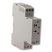
... Operating mode display window and selector (select the mode from and J for the H3DS-ML, from A, B2, E, and J for the H3DS-SL) H3DS-ALj Output indicator (orange) (Lit while Timer output is ON.) Set time window Time scale display window and selector (select one from 1 s, ...
Page 6
... Set the selector at a position at which it is secured. Do not set it midway between two securing positions or a malfunc- tion could result from improper setting. Selection of Operating Mode (except for H3DS-AL) The H3DS-ML/-SL can be set to any one of the operating modes Turn the operating mode selector with a screwdriver until the desired operating mode appears in the operating mode display win- dow ...
Page 7
... Output relay and 16 Output relay: NO (output indicator) 15 and 18 Power indicator Note: The start input of the H3DS-MLj model is activated by applying a voltage to B1 and A2 terminals. The voltage can be applied by turning on the contact between B1 and A1 (Refer to T erminal Arrangement ). 10 Timing chart t t– t– ...
Page 8
... Output relay 0.6 s (output indicator) (fixed) 15 and 18 Power indicator Note: The start input of the H3DS-MLj model is activated by applying a voltage to B1 and A2 terminals. The voltage can be applied by turning on the contact between B1 and A1 (Refer to T erminal Arrangement ). Timing chart t–a t–a t t–a ...
Page 9
... Terminal Arrangement H3DS-MLj (see note 1) Note supply voltage does not require the designation of polarity. 2. The contact symbol for the H3DS is indicated with contact for conventional timers. 12 Surface color: Light gray 5Y7/1 (OMRON) H3DS-SLj/-ALj (see note 1) because it offers multiple operating modes and is different from the delayed ...
Page 10
... H3DS Input Connections The inputs of the H3DS-MLj are voltage (voltage imposition or open) inputs. No-contact Input (Connection to PNP output sensor.) Sensor Timer (+) Start 24 VDC (– Operates with PNP transistor ON Voltage Input Signal Levels 1. Transistor ON Residual voltage max. (Voltage between terminals B No-contact input the rated “ ...
Page 11
... Note: The values shown in parentheses are for the PFP-50N. End Plate PFP pan head screw 14 PFP-100N2 7.3 0.15 4.5 27 0. (5) (see note) Spacer PFP-S 10 6.2 1.8 1 35.5 35.3 1.8 1.3 4.8 H3DS 0 1,000 34.8 44.3 16.5 29.2 1.5 ...
Page 12
... Timer. Both AC and DC power supplies can be connected to the power in- put terminals without regarding polarity. With the H3DS only power supply must be connected to the power input terminals as designated according to the polarity of the terminals power supply can be connected if its ripple factor is 20% or less and the mean voltage is within the rated operating voltage range of the Timer ...
Page 13
... The H3DS as a built-in timer conforms to EN61812-1 provided that the following conditions are satisfied: The output section of the H3DS is provided only with basic isolation. To ensure reinforced isolation required by the EN61812-1, provide supplementary basic isolation on the load side connected to the out- put ...