8321-0110 REDINGTON COUNTERS, 8321-0110 Datasheet - Page 2
8321-0110
Manufacturer Part Number
8321-0110
Description
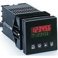
Digital Multifunction Timer
Manufacturer
REDINGTON COUNTERS
Datasheet
1.8321-0110.pdf
(4 pages)
Specifications of 8321-0110
Time Range
999999hr
Power Consumption
5.5W
Character Size
0.3"
Meter Function
Counter
Peak Reflow Compatible (260 C)
No
Signal Input Type
Run/Stop, User Input
Output Type
NPN OC/Relay
Lead Free Status / RoHS Status
Contains lead / RoHS non-compliant


Specifications
Annunciators:
POWER REQUIREMENTS:
PEAK (START-UP CURRENT)
DC OUT/ VSCR IN-terminal 10
For units that do not have PNP current sourcing outputs, this terminal
provides a DC output for sensor power (+ 12 VDC +/-15%). The
maximum sensor current is 100mA. For units with PNP current sourcing
outputs this terminal serves a dual purpose depending on the application
PNP output voltage level and current requirements.
3. MEMORY: Nonvolatile FRAM retains all program parameters and
4. SENSOR POWER: +12 VDC (+/- 15%) @ 100mA max.
5. INPUTS: Run/Stop, Usr. In1, Usr. In2, and Usr. In3.
Display:
Current Sinking: (active low) :
Current Sourcing: (active high): V IH = 3.5 min.
User Input Response Time: 5 msec. max.
Secondary:
Run/Stop Response Time : 250 microseconds max.
Main:
Note: Models with PNP current sourcing outputs must be
Value:
Output:
AC Versions
DC Versions
Note: The 10% tolerance range on AC input voltage must be
strictly adhered to> DO NOT EXCEED 26.4 VAC
AC or DC Power: 500mA peak start-up current for 10 msec.
max.
1.
2.
Model 83
Configurable as current sinking (active low), or
current sourcing (active high) inputs via a single
plug jumper.
powered from AC
Timer values.
If a higher PNP output voltage level or additional output
The terminal may be used as a +12 VDC output for sensor
power. In this case, the PNP output voltage level will be
+12 VDC (+/-15%). A maximum of 100 mA is available for
the combination of sensor and PNP output sourcing
current.
sourcing current is needed, an external DC supply may be
connected between the “DC OUT” ( V SRC IN) and
“COMM .” terminals. This supply will determine the PNP
output voltage level, and must be in the same range of +13
to +30 VDC.
An external DC supply can also provide the additional
output sourcing current required in applications where
two or more PNP outputs are “ON” simultaneously.
However, the maximum current range of 100mA per
individual output must not be exceeded, regardless of
external supply capacity.
AC Power: 85 to 250 VAC, 50/60Hz, 9VA max.
DC power: 11 to 14 VDC @ 159 mA max. (Non PNP
DC Power: 18 to 36 VDC: 5.5 W max.
AC Power: 24 VAC +/- 10%: 50/60 Hz: 7VA max.
V IL = 1.5 VDC max. 22 K ohm pull-ups to 5 VDC
V IN max. = 30 VDC; 22K ohm pull-down.
PRS, 1, and 2
2 line by 6 digits LCD display, negative image
transmissive with RED (top line) and GREEN
(bottom line) backlighting. Positive image reflective
display units are non-stock available.
0.3" (7.6mm) high digits
0.2" (5mm) high digits
01 and 02
output models)
www.redingtoncounters.com
Electronic
6. TIME ACCURACY: +/- 0.01%
7. OUTPUTS: ( Output type and quantity model dependent)
8. RS485 SERIAL COMMUNICATIONS (Optional):
9. CERTIFICATIONS AND COMPLIANCES:
10. ENVIRONMENTAL CONDITIONS:
Relay: Form A contact, rating = 5 A @ 250 VAC, 30 VDC (resistive
UL Recognized Component, File # E195514
Recognized to U.S. and Canadian requirements under the Component
Recognition Program of Underwriters Laboratories, Inc.
CE COMPLIANT :
ELECTROMAGNETIC COMPATIBILITY
Immunity to EN 50082-2
electrostatic discharge
electromagnetic RF fields
fast transients
RF conducted interference
simulation of cordless phone
Emissions to EN 50081-2
RF interference
Solid-State:
Note: The internal supply of the 83 Timer can provide a total of
100 mA for the combination of sensor current and PNP output
sourcing current. The supply voltage is +12 VDC (+/-5 %),
which will be the PNP output voltage level when using only the
internal supply.
If additional PNP output sourcing current or a higher output
voltage level is desired, an external DC supply may be
connected between the “ DC Out/In” and “Comm” terminals.
This supply will determine the PNP output voltage level, and
must be in range of +13 to 30 VDC.
An external supply can provide the additional output sourcing
current required in applications where two or more outputs are
“ON” simultaneously. However, the maximum rating of 100mA
per individual output must not be exceeded, regardless of
external supply capacity.
load) 1/10 HP @ 120 VAC (inductive load).
Relay Life Expectancy:
Programmable Timed Output:
Up to 32 units can be connected.
Baud Rate: Programmable from 1200 to 9600 baud.
Address: Programmable from 0 to 99
Data Format: 10 Bit Frame, 1 start bit , 7 or 8 data bits, 1 or
no Parity bit, and 1 stop bit.
Parity: Programmable for Odd (7 data bits), Even ( 7 data bits)
or None ( 8 data bits).
Operating Temperature: +32°F to +122°F [0°C to +50°C]
Storage Temperature: -40°F to +158°F [-40°C to +70°C]
NPN Open Collector:
PNP Open Collector:
I SNK = 100mA max. @ V OL = 1.1 VDC max.;
V OH = 30 VDC max.
I SRC = 100mA max. ( See note) ; V OH = 12 VDC +/-15%
( using internal supply); V OH = 13 to 30 VDC ( using
external supply).
100,000 cycles min. at max. load rating.
User selectable output time resolutions.
0.01 Second Resolution: 0.01 to 99.99 sec., +/-
0.1 Second Resolution: 0.1 to 999.9 sec. +/- 0.01
LCD Predetermining Timer
EN 55011
EN 61000-4-2
EN 61000-4-3
EN 61000-4-4
EN 61000-4-6
ENV50204
0.01% +10 msec max.
% +100 msec max.
enclosure class A
95
Related parts for 8321-0110
Image
Part Number
Description
Manufacturer
Datasheet
Request
R

Part Number:
Description:
Relay; SSR; Timing; Multi-Function; SPST-NO; Cur-Rtg 5A; Ctrl-V 85-250AC; Pnl-Mnt
Manufacturer:
Redington Counters, Inc.
Datasheet:

Part Number:
Description:
Panel Mount Bezel
Manufacturer:
REDINGTON COUNTERS
Datasheet:
Part Number:
Description:
Panel Mount Bezel
Manufacturer:
REDINGTON COUNTERS
Datasheet:

Part Number:
Description:
Panel Mount Bezel
Manufacturer:
REDINGTON COUNTERS
Datasheet:
Part Number:
Description:
ROTARY COUNTER, MECHANICAL, 29 SERIES
Manufacturer:
REDINGTON COUNTERS
Part Number:
Description:
Sealing Gasket
Manufacturer:
REDINGTON COUNTERS
Datasheet:

Part Number:
Description:
Sealing Gasket
Manufacturer:
REDINGTON COUNTERS
Datasheet:

Part Number:
Description:
Sealing Gasket
Manufacturer:
REDINGTON COUNTERS
Datasheet:

Part Number:
Description:
Sealing Gasket
Manufacturer:
REDINGTON COUNTERS
Datasheet:

Part Number:
Description:
Relay Module
Manufacturer:
REDINGTON COUNTERS
Datasheet:
Part Number:
Description:
AC Power Module
Manufacturer:
REDINGTON COUNTERS
Datasheet:

Part Number:
Description:
Electromechanical Totalizing Counter
Manufacturer:
REDINGTON COUNTERS
Part Number:
Description:
Rotary Counter
Manufacturer:
REDINGTON COUNTERS
Datasheet:
