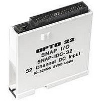
SNAP-ODC-32-SRC OPTO 22, SNAP-ODC-32-SRC Datasheet - Page 3

SNAP-ODC-32-SRC
Manufacturer Part Number
SNAP-ODC-32-SRC
Description
I/O Module
Manufacturer
OPTO 22
Type
Outputr
Specifications of SNAP-ODC-32-SRC
Leaded Process Compatible
No
Peak Reflow Compatible (260 C)
No
Signal Input Type
5VDC
No. Of Analog Outputs
32
No. Of Outputs
32
Brand/series
SNAP Series
Connection To Host
Backplane
Current, Input
150 mA
Dimensions
82.55mmL×18.29mmW×82.8mmH
Mounting Type
DIN Rail
Number Of Channels
32
Output
5 to 60 VDC
Output Type
Digital
Output, Range
5 to 60 VDC
Primary Type
Control
Voltage, Supply
5 VDC
Lead Free Status / RoHS Status
Contains lead / RoHS non-compliant
PAGE
6
Specifications (continued)
Switching Voltage
Nominal Switching Voltage
Logic Voltage and Current
Output Arrangement
Maximum Number of HDD
Modules on One Mounting Rack
Indicators
Polling time from I/O processor to
module
Output Turn-On/Off Time
Maximum Load per Point
Forward Drop
Maximum Off State Voltage
Reverse Voltage
Surge (1 sec.)
1 Affects turn-on and turn-off determination
2 Time varies based on the SNAP PAC I/O processor (brain or on-the-rack controller), processor configuration, and Ethernet host
communication activity.
1
5–60 VDC
12–24 VDC
5 VDC ± 0.1 @ 150 mA
32 output channels; 4 groups of 8 outputs
each. Points in each group share a common
positive connection.
16
None; use optional OptoTerminal-G20
diagnostic display or breakout rack.
2–30 ms typical
100 microseconds
0.25 A
0.15 VDC @ 0.25 A
60 VDC
0.6 VDC
1 A
SNAP High-Density Digital I/O Modules
SNAP-ODC-32-SRC
2
5–60 VDC
12–24 VDC
5 VDC ± 0.1 @ 150 mA
32 output channels; 4 groups of 8 outputs
each. Points in each group share a common
negative connection.
16
None; use optional OptoTerminal-G20
diagnostic display or breakout rack.
2–30 ms typical
100 microseconds
0.25 A
0.15 VDC @ 0.25 A
60 VDC
0.6 VDC
1 A
SNAP-ODC-32-SNK
2


