SNAP-PAC-RCK8 OPTO 22, SNAP-PAC-RCK8 Datasheet - Page 6
SNAP-PAC-RCK8
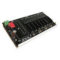
Manufacturer Part Number
SNAP-PAC-RCK8
Description
Mounting Rack
Manufacturer
OPTO 22
Type
Mounting Racksr
Datasheet
1.SNAP-PAC-RCK8.pdf
(7 pages)
Specifications of SNAP-PAC-RCK8
Accessory Type
8 Module Mounting Rack
Leaded Process Compatible
No
Peak Reflow Compatible (260 C)
No
Mounting Type
Rack Mount
For Use With
SNAP I/O Modules
Lead Free Status / RoHS Status
Contains lead / RoHS non-compliant


PAGE
6
Assembling the Circuit Board, Rack Extrusion, and Din Clips,
Opto 22 • 43044 Business Park Drive • Temecula, CA 92590-3614 • www.opto22.com
SALES 800-321-6786 • 951-695-3000 • FAX 951-695-3095 • sales@opto22.com • SUPPORT 800-835-6786 • 951-695-3080 • FAX 951-695-3017 • support@opto22.com
© 2007–2010 Opto 22. All rights reserved. Dimensions and specifications are subject to change. Brand or product names used herein are trademarks or registered trademarks of their respective companies or organizations.
Removing the Circuit Board from the Rack Extrusion
If end caps are present, remove them. Then insert a flathead screwdriver in one of
the circuit board release notches and pry up the board. Repeat in the other
release notches until the board pops out of the extrusion.
1.
2.
3.
4.
5.
(This step only for racks with three or more clips.)
Slide one DIN clip to the middle position and
secure with the rivet provided. For racks with four
clips, add an additional middle clip.
Using the screws provided, secure an end cap
and DIN clip assembly to each end of the
extrusion.
Insert one edge of the circuit board into the
extrusion.
Push down hard on the other edge to snap
the board into place.
Attach one DIN clip to each end cap using
the slots in the end caps as shown.
3
SNAP PAC Racks
Rivet
2
Related parts for SNAP-PAC-RCK8
Image
Part Number
Description
Manufacturer
Datasheet
Request
R

Part Number:
Description:
SNAP PAC Ethernet Brain, Ana/Dig/Ser With High-speed Digital Counting-FM Approved
Manufacturer:
OPTO 22
Part Number:
Description:
SNAP PAC Ethernet Brain, Analog/Digital/Serial-FM Approved
Manufacturer:
OPTO 22
Part Number:
Description:
SNAP PAC R-series Programmable Automation Controller-FM Approved
Manufacturer:
OPTO 22
Part Number:
Description:
SNAP PAC R-series Programmable Automation Controller On-The-Rack-FM Approved
Manufacturer:
OPTO 22

Part Number:
Description:
SNAP PAC S-series Programmable Automation Controller-FM Approved
Manufacturer:
OPTO 22
Datasheet:
Part Number:
Description:
SNAP Multifunction 12 Module Rack-FM Approved
Manufacturer:
OPTO 22
Part Number:
Description:
SNAP Multifunction 16 Module Rack-FM Approved
Manufacturer:
OPTO 22
Part Number:
Description:
SNAP Multifunction 4 Module Rack-FM Approved
Manufacturer:
OPTO 22
Part Number:
Description:
SNAP Multifunction 8 Module Rack-FM Approved
Manufacturer:
OPTO 22
Part Number:
Description:
I/O Processor
Manufacturer:
OPTO 22
Datasheet:

Part Number:
Description:
Solid State Relays, Accessories
Manufacturer:
OPTO 22
Datasheet:
