750-304 WAGO, 750-304 Datasheet
750-304
Manufacturer Part Number
750-304
Description
BUSCOUPLER STD. IBUS-S
Manufacturer
WAGO
Datasheet
1.750-304.pdf
(2 pages)
Specifications of 750-304
Rohs Compliant
NA


100
1
WAGO Kontakttechnik GmbH & Co. KG
Subject to design changes
Description
INTERBUS 500 kBd
Accessories
INTERBUS files
Miniature WSB Quick marking system
Standards and Approvals
Standard
Certification
Conformity marking
r UL 508
4 r ANSI/ISA 12.12.01
4 EN 60079-15
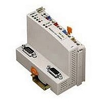
750-304
INTERBUS Fieldbus Coupler
500 Kbaud; digital and analog signals
This buscoupler connects the WAGO-I/O-SYSTEM as a slave to the INTERBUS
fieldbus.
The buscoupler automatically configures, creating a local process image which
may include analog, digital or specialty modules. Analog and specialty
module data is sent via words and/or bytes, digital data is sent bit by bit.
INTERBUS stores the process image in the corresponding Master control (PLC,
PC or NC).
with marking
plain
EN 50254
INTERBUS CLUB
1
I M2 / II 3 GD Ex nA IIC T4
Class I, Div. 2, Grp. ABCD, T4
18.02.2010
Item No.
750-304
Item No.
Download: www.wago.com
248-501
see pages 304 ... 305
Fieldbus
connection
D-Sub,
Input
Fieldbus
connection
D-Sub,
Output
Configuration
interface
Postfach 2880 - D-32385 Minden
Hansastr. 27 - D-32423 Minden
Pack.
Unit
1
Pack.
Unit
5
The local process image is divided into two data zones containing the data
received and the data to be sent. The process data can be sent via the
INTERBUS fieldbus to the PLC, PC or NC for further processing, and received
from the field via INTERBUS. The process data can be sent via the INTERBUS
fieldbus to the PLC, PC or NC for further processing, and received from the field
via INTERBUS.
The data of the analog modules is stored in the process image which is created
automatically according to the order in which the modules are connected to the
buscoupler. The bits of the digital modules are sent byte by byte and added to
the analog data. If the amount of digital information exceeds 8 bits, the
buscoupler automatically starts with a new byte.
System Data
No. of couplers connected to Master
Max. no. of I/O points
Transmission medium
Max. length of fieldbus segment
Baud rate
Transmission time
Buscoupler connection
INTERBUS
READY
BA
RC
RD
I/O
Phone: +49(0)571/887-0
Fax: +49(0)571/887-169
A
B
24V 0V
01 02
—
+
+
—
C
D
256
4096 (depends on master)
Certified Cu cable
400 m
500 Kbaud
typ. 1.43 ms (10 couplers; 32 digital I/Os
per coupler)
1 x D-Sub 9; plug for input interface
1 x D-Sub 9; socket for output interface
Status
voltage supply
-System
-Power jumper contacts
Data contacts
Supply
24 V
0 V
Supply via
power jumper contacts
24 V
0 V
Power jumper contacts
E-Mail: info@wago.com
www.wago.com
Related parts for 750-304
Image
Part Number
Description
Manufacturer
Datasheet
Request
R


Part Number:
Description:
2 CHAN OUT RELAY 2A 230VAC
Manufacturer:
WAGO
Datasheet:
Part Number:
Description:
2-CHANNEL RELAY OUTPUT MODULE
Manufacturer:
WAGO
Datasheet:

Part Number:
Description:
4 CHAN DIG INPUT 5VDC .2mS
Manufacturer:
WAGO
Datasheet:

750-304 Summary of contents
Page 1
... The bits of the digital modules are sent byte by byte and added to the analog data. If the amount of digital information exceeds 8 bits, the buscoupler automatically starts with a new byte. Pack. System Data Item No. Unit 750-304 1 No. of couplers connected to Master Max. no. of I/O points Transmission medium Max. length of fieldbus segment Baud rate ...
Page 2
... Technical Data Number of I/O modules 64 Fieldbus Max. input process image 64 bytes Max. output process image 64 bytes Configuration via PC or PLC Voltage supply (-15 % ... +20 %) Max. input current (24 V) 500 mA Efficiency of the power supply 87 % Internal current consumption (5 V) 300 mA (as from version 0101), ...