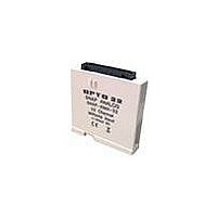
SNAP-AIV-32 OPTO 22, SNAP-AIV-32 Datasheet - Page 2

SNAP-AIV-32
Manufacturer Part Number
SNAP-AIV-32
Description
I/O Module
Manufacturer
OPTO 22
Type
Inputr
Specifications of SNAP-AIV-32
Accessory Type
I/O Module
Leaded Process Compatible
No
Peak Reflow Compatible (260 C)
No
Brand/series
SNAP Series
Connection To Host
Backplane
Current, Input
150 mA
Dimensions
82.55mmL×18.29mmW×90.17mmH
Input
-10 to +10/-5 to +5 VDC
Input Type
Analog
Input, Range
-10 to +10/-5 to +5 VDC
Mounting Type
PCB
Number Of Channels
32
Primary Type
Control
Special Features
Transformer Isolation, Optical Isolation
Voltage, Isolation
1500 V
Voltage, Supply
5 VDC
For Use With
SNAP PAC Brains
Lead Free Status / RoHS Status
Contains lead / RoHS non-compliant
PAGE
26
Voltage Input Module, -10 VDC to +10 VDC or -5 VDC to +5 VDC,
32 Channels
Specifications
Input Range
Resolution
Input Filtering
Data Freshness (Max) 1.1 s
DC Common Mode
Rejection
AC Common Mode
Rejection
Maximum Survivable
Input
Maximum Operating
Common Mode Volt-
age
Accuracy
Gain Temperature
Coefficient
Offset Temperature
Coefficient
Isolation
Power Requirements
Input Resistance
Ambient Temperature:
Operating
Storage
From -10 volts to +10 volts
From -5 volts to +5 volts
0.4 mV when configured -10 to +10
volts
0.2 mV when configured -5 to +5 volts
-3 dB @ 31 Hz
>-120 dB
>-120 dB @ 60 Hz
220 VAC or 300 VDC
250 V
0.05%, 5 mV @ 10 VDC
2.5 mV @ 5 VDC
30 PPM/ °C
15 PPM/ °C
1500 V
5 VDC (±0.15) @ 150 mA
1 M ohms (each channel; all channels
share the same reference point)
0 °C to 70 °C
-25 °C to 85 °C
Description
The SNAP-AIV-32 and SNAP-AIV-32-FM modules can be
configured for either -10 VDC to +10 VDC or -5 VDC to +5 VDC
operation on each of its 32 channels. See the table on
processor compatibility. The SNAP-AIV-32-FM is Factory Mutual
approved.
Note that all channels share a common reference terminal. (For
channel-to-channel isolated modules, see Opto22 form #1182.)
SNAP TEX cables and a breakout rack are available separately for
wiring points to field devices (see form #1756, the SNAP TEX Cables
& Breakout Boards Data Sheet). The SNAP-HD-BF6 wiring harness
connects the module to the breakout rack, which can then be wired
to field devices. The SNAP-HD-CFB6 wiring harness has flying leads
to connect to field devices.
See the dimensional drawing for the module on
SNAP-AIV-32
SNAP-AIV-32-FM
SNAP-HD-CBF6
SNAP-HD-BF6
SNAP-AIV-HDB
SNAP-AIV-HDB-FM
SNAP Analog Input Modules
Part Number
32-channel analog voltage input -10 to
+10 VDC
Wiring harness with flying leads for
SNAP-AIV-32 modules
Wiring harness for SNAP-AIV-32 mod-
ules and SNAP-AIV-HDB breakout racks
Breakout racks for SNAP-AIV-32 and
SNAP-AIV-32-FM
Description
page
page 2
31.
for I/O


