KFD2-SR2-EX-1.W PEPPERL & FUCHS, KFD2-SR2-EX-1.W Datasheet - Page 2
KFD2-SR2-EX-1.W
Manufacturer Part Number
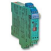
KFD2-SR2-EX-1.W
Description
ISOLATION AMPLIFIER
Manufacturer
PEPPERL & FUCHS
Datasheet
1.KFD2-SR2-EX-1.W.pdf
(4 pages)
Specifications of KFD2-SR2-EX-1.W
Input Type
Intrinsically Safe
Output Type
Relay
No. Of Output Channels
1
No. Of Input Channels
1
Supply Voltage Range
20VDC To 30VDC
Isolation Input
Isolated
Operating Temperature Max
60°C
No. Of Channels
1
No. Of Outputs
1
Operating Temperature Range
-20°C To +60°C
Signal Conditioner Input
Digital
Signal Conditioner Output
Relay


Subject to reasonable modifications due to technical advances.
Pepperl+Fuchs Group • Tel.: Germany (06 21) 7 76-0 • USA (330) 4 25 35 55 • Singapore (6) 7 79 90 91 • Internet http://www.pepperl-fuchs.com
Power supply
Connection type
Rated operational voltage
Rated operational current
Safety maximum voltage U
Ripple
Input (intrinsically safe)
Connection type
Nominal data
Quiescent voltage/Short-circuit current
Switching point/Switching hysteresis
Input pulse length/Input pulse interval
Lead monitoring
Details of certificate of conformity
Certification number
Group, category, ignition protection method
Allowable circuit values
Ignition protection class, category [EEx ia and
EEx ib]
Entity parameter
Certification number
FM control drawing
Suitable for installation in division 2
Connection type
Input I
Safety parameter
UL control drawing
CSA control drawing
Control drawing
Connection type
Input I
Output (not intrinsically safe)
Connection type
Output
Contact loading
Mechanical life
Energized/De-energized delay
Transfer characteristics
Switching frequency
Galvanic isolation
Input/Output
Input/Power supply
Technical data
Voltage U
Current I
Power
Explosion group
External capacitance
External inductance
Voltage V
Current I
Explosion group
Max. external capacitance C
Max. external inductance L
Safety parameter
Voltage V
Current I
Explosion group
Max. external capacitance C
Max. external inductance L
SC
SC
P
OC
OC
0
0
0
m
a
a
a
a
Power Rail or terminals 14+, 15-
20 ... 30 V DC
20 ... 23 mA
40 V DC
£ 10 %
terminals 1+, 2+, 3-
in accordance with IEC 60947-5-6 (NAMUR, DIN 19234); see system description for electrical
data
approx. 8 V DC / approx. 8 mA
1.2 ... 2.1 mA / approx. 0.2 mA
Š 20 ms / Š 20 ms
breakage J £ 0.1 mA , short-circuit J > 6 mA
PTB 00 ATEX 2080 ; for additional certifications refer to the approval list
¬ II (1) G D [EEx ia] IIC
10.5 V
13 mA
34 mW
IIA
75 µF
1000 mH
J.I.3002773
No. 116-0035
yes
terminals 1, 3; 2, 3; 4, 6; 5, 6
12.9 V
19.8 mA
A&B
1.273 µF
84.8 mH
E 106378
LR 36087-13
No. 116-0047
terminals 1, 3; 2, 3; 4, 6; 5, 6
12.6 V / 650 Ohm
12.9 V
19.8 mA
A&B
1.273 µF
84.88 mH 298.7 mH 744.4 mH
terminals 7, 8, 9
signal ; relay
253 V AC / 2 A / cos j > 0.7; 40 V DC / 2 A ohmic load; from january 2002 increase of the con-
tact rating to 4 A for 115 V AC switching voltage. The respective connection data are shown
on the type plate.
10
approx. 20 ms / approx. 20 ms
< 10 Hz
safe galvanic isolation acc. to EN 50020, voltage peak value 375 V
safe galvanic isolation acc. to EN 50020, voltage peak value 375 V
7
switchings
IIB
16.8 µF
840 mH
C&E
3.82 µF
254.4 mH 678.4 mH
C&E
3.82 µF
IIC
2.41 µF
210 mH
D, F&G
10.18 µF
D, F&G
10.18 µF
Copyright Pepperl+Fuchs, Printed in Germany
KFD2-SR2-Ex1.W
2
Related parts for KFD2-SR2-EX-1.W
Image
Part Number
Description
Manufacturer
Datasheet
Request
R

Part Number:
Description:
Isolator Switch
Manufacturer:
PEPPERL & FUCHS
Datasheet:

Part Number:
Description:
SINGLE CHANNEL, 1 FORM C RELAY OUTPUT, LINE MONITORING W/COMMON FAULT, SIL 2 (I
Manufacturer:
PEPPERL & FUCHS
Part Number:
Description:
SINGLE CHANNEL, 2 FORM C RELAY OUTPUTS, SELECTABLE LINE MONITORING W/COMMON FAU
Manufacturer:
PEPPERL & FUCHS
Part Number:
Description:
DUAL CHANNEL, 2 N.O. RELAY OUTPUTS/CH, LINE MONITORING W/COMMON FAULT, SIL 2 (I
Manufacturer:
PEPPERL & FUCHS
Part Number:
Description:
DUAL CHANNEL, 1 FORM C RELAY OUT/CH, LINE MONITORING W/COMMON FAULT, DIRECTION/STANDSTILL DETECT, 24VDC
Manufacturer:
PEPPERL & FUCHS
Part Number:
Description:
WE77/EX-1 230V, PEPPERL + FUCHS, SWITCH ISOLATOR 230V
Manufacturer:
PEPPERL & FUCHS
Datasheet:
Part Number:
Description:
Rotary Encoders - Absolute
Manufacturer:
PEPPERL & FUCHS


Part Number:
Description:
LED Pilot Light
Manufacturer:
PEPPERL & FUCHS
Datasheet:

Part Number:
Description:
LED Pilot Light
Manufacturer:
PEPPERL & FUCHS
Datasheet:
Part Number:
Description:
LED Pilot Light
Manufacturer:
PEPPERL & FUCHS
Datasheet:
Part Number:
Description:
LED Pilot Light
Manufacturer:
PEPPERL & FUCHS
Datasheet: