CUB4L8W0 Red Lion Controls, CUB4L8W0 Datasheet - Page 2
CUB4L8W0
Manufacturer Part Number
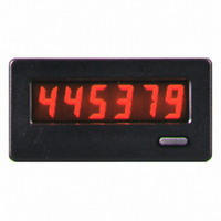
CUB4L8W0
Description
8-Digit Counter Positive Reflective
Manufacturer
Red Lion Controls
Series
CUB4r
Type
Electronic Counterr
Datasheet
1.CUB4L8W0.pdf
(4 pages)
Specifications of CUB4L8W0
Count Rate
30Hz or 5kHz Selectable
Number Of Digits/alpha
8
Input Type
Switch Closure or Transistor Switch
Voltage - Supply
None Required (Battery Included)
Display Type
LCD Non-Backlit
Application
Miniature Electronic Counter
Brand/series
CUB4
Dimensions
1.54 H × 2.95 W × 1.51 D In.
Display Digit Height
0.46"
Mounting Type
Panel
Number Of Digits
8
Primary Type
Counter
Signal, Input
Switch Contact or Open Collector Transistor
Termination
Screw Clamp
Voltage, Supply
3 Volt Batteries
Operating Temp.
0 to 60°C
Lead Free Status / RoHS Status
Lead free / RoHS Compliant
Output Type
-
Lead Free Status / RoHS Status
Lead free / RoHS Compliant
Other names
Q1954419


5. ENVIRONMENTAL CONDITIONS:
6. CERTIFICATIONS AND COMPLIANCES:
7. CONSTRUCTION:
8. WEIGHT: 3 oz. (85 grams)
INSTALLATION ENVIRONMENT
operating temperature and provides good air circulation. Placing the unit near
devices that generate excessive heat should be avoided.
Do NOT use solvents. Continuous exposure to direct sunlight may accelerate
the aging process of the bezel.
keypad of the unit.
Installation
use, when properly installed. The units are intended to be mounted into an
enclosed panel. The viewing window and reset button are factory sealed for a
washdown environment. A sponge rubber gasket and mounting clip are
provided for sealing the unit in the panel cut-out.
1. Cut panel opening to specified dimensions. Remove burrs and clean around
2. Carefully remove the center section of the panel gasket and discard.
3. Assemble nut fastener first and then mounting screw onto both sides of
4. Install CUB4 unit through the panel cut-out until front bezel flange contacts
5. Slide the mounting clip over the rear of the unit until the mounting clip is
Operating Temperature: 0 to 60°C (above 50°C, derate backlight operating
Storage Temperature: -30 to 85°C
Operating and Storage Humidity: 85% max. (non-condensing) from 0°C to
Vibration According to IEC 68-2-6: 5 to 500 Hz, in X, Y, Z direction for 1.5
Shock According to IEC 68-2-27: Operational 30 g, 11 msec in 3 directions.
Altitude: Up to 2000 meters
SAFETY
ELECTROMAGNETIC COMPATIBILITY
Refer to the EMC Installation Guidelines section of this bulletin for
This unit is rated for NEMA 4X/IP65 indoor use. Installation Category I,
Pollution Degree 2
The unit should be installed in a location that does not exceed the maximum
The bezel should be cleaned only with a soft cloth and neutral soap product.
Do not use tools of any kind (screwdrivers, pens, pencils, etc.) to operate the
The CUB4 series of products meet NEMA 4X/IP65 requirements for indoor
The following procedure assures proper installation:
panel opening.
Slide gasket over rear of the unit to the back of the bezel.
mounting clip. Tip of screw should not project from hole in mounting clip.
the panel-mounted gasket.
against the back of the panel. The mounting clip has latching features which
engage into mating features on the CUB4 housing.
Note: It is necessary to hold the unit in place when sliding mounting clip into
CUB4L8 & CUB4L8W: 15 msec min. pulse width (active low) from 3.0 V
voltage to 26 VDC max.).
50°C.
hours, 5g’s.
UL Recognized Component, File # E179259, UL 61010-1, CSA C22.2 No.
Type 4X Enclosure rating (Face only), UL50
IECEE CB Scheme Test Certificate # US/9257C/UL,
additional information.
Immunity to EN 50082-2
Electrostatic discharge
Electromagnetic RF fields
Fast transients (burst)
RF conducted interference
Power frequency magnetic fields
Simulation of cordless telephone
Emissions to EN 50081-2
RF interference
position.
bipolar output or an open collector transistor or a switch contact to
common.
61010-1
Recognized to U.S. and Canadian requirements under the Component
Recognition Program of Underwriters Laboratories, Inc.
CB Scheme Test Report # E179259-V01-S02
IEC 61010-1, EN 61010-1: Safety requirements for electrical
IP65 Enclosure rating (Face only), IEC 529
Issued by Underwriters Laboratories, Inc.
equipment for measurement, control, and laboratory use, Part 1.
EN 61000-4-2
EN 61000-4-3
EN 61000-4-4
EN 61000-4-6
EN 61000-4-8
ENV 50204
EN 55011
Level 2; 4 Kv contact
Level 3; 8 Kv air
Level 3; 10 V/m
80 MHz - 1 GHz
Level 4; 2 Kv I/O
Level 3; 2 Kv power
Level 3; 10 V/rms
150 KHz - 80 MHz
Level 4; 30 A/m
Level 3; 10 V/m
900 MHz ± 5 MHz
200 Hz, 50% duty cycle
Class B
2
EMC INSTALLATION GUIDELINES
immunity to Electromagnetic Interference (EMI), proper installation and wiring
methods must be followed to ensure compatibility in each application. The type
of the electrical noise, source or coupling method into a unit may be different
for various installations. Cable length, routing, and shield termination are very
important and can mean the difference between a successful or troublesome
installation. Listed are some EMI guidelines for a successful installation in an
industrial environment.
1. Use shielded (screened) cables for all Signal and Control inputs. The shield
2. Never run Signal or Control cables in the same conduit or raceway with AC
3. Signal or Control cables within an enclosure should be routed as far away as
4. In extremely high EMI environments, the use of external EMI suppression
5. Long cable runs are more susceptible to EMI pickup than short cable runs.
6. Alternately tighten each screw to ensure uniform gasket pressure. Visually
7. If gasket is not adequately compressed, and mounting screws can no longer
Although Red Lion Controls Products are designed with a high degree of
(screen) pigtail connection should be made as short as possible. The
connection point for the shield depends somewhat upon the application.
Listed below are the recommended methods of connecting the shield, in order
of their effectiveness.
a. Connect the shield only at the panel where the unit is mounted to earth
b. Connect the shield to earth ground at both ends of the cable, usually when
c. Connect the shield to common of the unit and leave the other end of the
power lines, conductors feeding motors, solenoids, SCR controls, and
heaters, etc. The cables should be run in metal conduit that is properly
grounded. This is especially useful in applications where cable runs are long
and portable two-way radios are used in close proximity or if the installation
is near a commercial radio transmitter.
possible from contactors, control relays, transformers, and other noisy
components.
devices, such as ferrite suppression cores, is effective. Install them on Signal
and Control cables as close to the unit as possible. Loop the cable through the
core several times or use multiple cores on each cable for additional protection.
Install line filters on the power input cable to the unit to suppress power line
interference. Install them near the power entry point of the enclosure. The
following EMI suppression devices (or equivalent) are recommended:
Ferrite Suppression Cores for signal and control cables:
Line Filters for input power cables:
Note: Reference manufacturer’s instructions when installing a line filter.
Therefore, keep cable runs as short as possible.
inspect the front panel gasket. The gasket should be compressed about 75 to
80% of its original thickness. (Recommended torque is 28 to 36 in-oz.) If
not, gradually turn mounting screws to further compress gasket.
be turned, loosen mounting screws and check that mounting clip is latched
as close as possible to panel.
Repeat procedure for tightening mounting screws.
ground (protective earth).
the noise source frequency is above 1 MHz.
shield unconnected and insulated from earth ground.
Fair-Rite # 0443167251 (RLC #FCOR0000)
TDK # ZCAT3035-1330A
Steward #28B2029-0A0
Schaffner # FN610-1/07 (RLC #LFIL0000)
Schaffner # FN670-1.8/07
Corcom #1VR3
Related parts for CUB4L8W0
Image
Part Number
Description
Manufacturer
Datasheet
Request
R

Part Number:
Description:
CUB 2 MIN. ELEC. COUNTER
Manufacturer:
Red Lion Controls
Datasheet:
Part Number:
Description:
CUB 4/5, DT8 NEMA 4X, Use With MLPS
Manufacturer:
Red Lion Controls
Part Number:
Description:
Counter
Manufacturer:
Red Lion Controls
Datasheet:
Part Number:
Description:
Miniature Length Sensor
Manufacturer:
Red Lion Controls
Datasheet:
Part Number:
Description:
Model Lsc - Single Channel Output Length Sensor
Manufacturer:
Red Lion Controls
Datasheet: