HWK60000 Red Lion Controls, HWK60000 Datasheet - Page 3
HWK60000
Manufacturer Part Number
HWK60000
Description
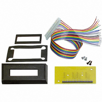
Bezel Kit, SCUBD
Manufacturer
Red Lion Controls
Datasheet
1.DM-OSC-B04A.pdf
(5 pages)
Specifications of HWK60000
Accessory Type
Bezel Kit
Lead Free Status / RoHS Status
Lead free / RoHS Compliant
For Use With/related Products
SubCub 2-8A, D, T
Lead Free Status / RoHS Status
Lead free / RoHS Compliant
Other names
HWK-60-000/A
HWK-60000
HWK6
RLC10
HWK-60000
HWK6
RLC10


TIME BASE SELECTION
seconds in 3.906 msec (1/256 second) increments. The minimum time base
setting is obtained by pulling only the TB1 input low while the maximum time
base is obtained by pulling all TB inputs low. Therefore, a specific time base
is achieved by adding the appropriate individual time base increments. The
time base increment total is computed according to the following formula:
WHERE:
EXAMPLE: Find the appropriate Time Base input settings for a desired
low to generate the desired time base. The actual time base in seconds is
calculated by dividing the TBIT Total by 256.
FREQUENCY DOUBLING
twice the number of input pulses are registered on the readout. This doubling
of the signal input rate allows the Time Base Increment Total (TBIT) to be
halved, thus allowing for a faster update time for a given display value. If this
input is in the low state, Frequency Doubling is disabled.
The SUB-CUB-R has a time base selection range of approx. 3.9 msec to 15.9
DR
DDP =
RPM =
PPR
DDP:
0
0.0
0.00
display reading with a fixed shaft speed.
DESIRED READING (DR)
REVOLUTIONS PER MINUTE (RPM) = 1250
PULSES PER REVOLUTION (PPR)
TBIT = 614 (round off to the nearest whole number)
As shown above, Time base inputs TB10, TB7, TB6, TB3, TB2 are pulled
FD is the Frequency Doubling input. When it is in the high state or left open,
TIME BASE
INPUT
=
=
=
=
=
TB1
TB2
TB3
TB4
TB5
TB6
TIME BASE INPUT
Desired Reading
Display Decimal Point
Revolutions Per Minute
Pulses Per Revolution
1
10
100 placement in the readout.
TBIT =
TB10 (512) . . . . . . . . .
TB7 (64)
TB6 (32)
TB3 (4)
TB2 (2)
TIME BASE INCREMENT
The Display Decimal Point (DDP) value is
determined by the desired decimal point
TOTAL (TBIT)
INCREMENT
TIME BASE
250.0 x 10 x 15,360
16
32
1
2
4
8
. . . . . . . . .
. . . . . . . . .
. . . . . . . . .
. . . . . . . . .
614/256 = 2.398 sec.
1250 x 50
REMAINDER NEEDED
=
614 - 512 = 102
102 - 64 = 38
38 - 32 = 6
6 - 4 = 2
2 - 2 = 0
=
DR x DDP x 15,360
= 250.0
= 50
TIME BASE
38,400,00
INPUT
TB10
62,500
TB11
TB12
RPM x PPR
TB7
TB8
TB9
= 614.4
INCREMENT
TIME BASE
1024
2048
128
256
512
64
3
DECIMAL POINT SELECTION
inputs. The table below shows the logic states which should be used to obtain
the desired decimal point location.
blanking. Note that a change in decimal point position will only occur at the
end of the present time base period.
PULSED PULL-UP LATCHED INPUTS
Doubling inputs are designed to be actuated by wired or switched
connection to Common or by switching an open collector of a transistor to
Common. A pull-up resistance is provided for all of these inputs. To keep
current consumption to a minimum, this input circuit has been designed to
latch the present state of the inputs, allowing the pull-up resistance to be
switched on and off, thus reducing current consumption. The following is
a description of the sequence of events for these inputs (Refer to the
drawing below):
the time base chip which will cause Q1 to switch ON the input’s pull-up
resistance. During this time, if the input is being held low, the input will
provide a sourcing current pulse thru Q1. The level of the input (either low
or high) is sensed by the input’s Latching Circuit. When the pulse is
terminated, the Latching Circuit will hold the input at its present state.
Latching Circuit will respond immediately and latch the input in the low
state. If an input is presently held in the low state, and is allowed to float,
the Latching Circuit cannot respond until the end of the time base; at which
time, the Pulsed Pull-up resistance will pull the input high. The Latching
Circuit will then latch the high state. A Master Reset (MR) will terminate
the present time base and allow new TB inputs to be latched.
The selection of the Decimal Point is accomplished by the DPA and DPB
The Time base inputs, the Decimal Point inputs, and the Frequency
At the end of a previous time base, a 30.5 µsec pulse is generated within
If an input, which is presently in the high state, is pulled low, the
High/Open
High/Open
DPB
Low
Low
High/Open
High/Open
Low
Low
DPA
The SUB-CUB-R has leading zero
Factory Test Mode Only
D.P. LOCATION
0.00
0.0
0
Related parts for HWK60000
Image
Part Number
Description
Manufacturer
Datasheet
Request
R

Part Number:
Description:
Counter
Manufacturer:
Red Lion Controls
Datasheet:
Part Number:
Description:
Miniature Length Sensor
Manufacturer:
Red Lion Controls
Datasheet:
Part Number:
Description:
Model Lsc - Single Channel Output Length Sensor
Manufacturer:
Red Lion Controls
Datasheet: