LSM-1.5/10-D5-C Murata Power Solutions Inc, LSM-1.5/10-D5-C Datasheet - Page 5
LSM-1.5/10-D5-C
Manufacturer Part Number
LSM-1.5/10-D5-C
Description
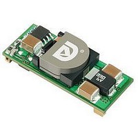
DC/DC Converter
Manufacturer
Murata Power Solutions Inc
Series
LSMr
Datasheet
1.LSM-2.510-D5-C.pdf
(13 pages)
Specifications of LSM-1.5/10-D5-C
Dc / Dc Converter O/p Type
Fixed
No. Of Outputs
1
Input Voltage
4.5V To 5.5V
Power Rating
15W
Output Voltage
1.5V
Output Current
10A
Approval Bodies
EN, IEC, UL
Supply Voltage
5V
Product
Non-Isolated / POL
Output Power
15 W
Input Voltage Range
4.5 V to 5.5 V
Number Of Outputs
1
Output Voltage (channel 1)
1.5 V
Output Current (channel 1)
10 A
Output Type
Low Voltage
Lead Free Status / RoHS Status
Lead free / RoHS Compliant


On/Off Control
The On/Off Control pin may be used for remote on/off operation. LSM D5
Series DC/DC converters are designed so that they are enabled when the
control pin is left open (open collector) and disabled when the control pin is
pulled low (to less than +0.8V relative to Common). As shown in Figure 4, all
models have an internal 5kΩ pull-up resistor to V
Dynamic control of the on/off function is best accomplished with a mechanical
relay or open-collector/open-drain drive circuit (optically isolated if appropri-
ate). The drive circuit should be able to sink appropriate current when
activated and withstand appropriate voltage when deactivated.
Applying an external voltage to the On/Off Control pin when no input power is
applied to the converter can cause permanent damage to the converter. The
on/off control function, however, is designed such that the converter can be
disabled (control pin pulled low) while input voltage is ramping up and then
"released" once the input has stabilized (see also power-up sequencing).
Power-up sequencing
If a controlled start-up of one or more LSM D5 Series DC/DC converters
is required, or if several output voltages need to be powered-up in a given
sequence, the On/Off control pin can be driven with an external open collector
device as per Figure 5.
Leaving the input of the external circuit open during power-up will have the
output of the DC/DC converter disabled. When the input to the external open
collector is pulled low, the DC/DC converters output will be enabled.
Output Overvoltage Protection
LSM D5 SMT Series DC/DC converters do not incorporate output overvolt-
age protection. In the extremely rare situation in which the device’s feedback
loop is broken, the output voltage may run to excessively high levels (V
V
all possible overvoltage situations, voltage limiting circuitry must be provided
external to the power converter.
IN
Figure 4. Driving the On/Off Control Pin with an Open-Collector Drive Circuit
). If it is absolutely imperative that you protect your load against any and
ON/OFF pin open: Logic High = DC/DC converter On
ON/OFF pin <0.4V: Logic Low = DC/DC converter Off
www.murata-ps.com
IN
(+Input).
Single Output, Non-Isolated, 5V
OUT
=
Output Overcurrent Detection
Overloading the power converter's output for an extended time will invariably
cause internal component temperatures to exceed their maximum ratings and
eventually lead to component failure. High-current-carrying components such
as inductors, FET's and diodes are at the highest risk. LSM D5 SMT Series
DC/DC converters incorporate an output overcurrent detection and shutdown
function that serves to protect both the power converter and its load.
If the output current exceeds it maximum rating by typically 70% (17 Amps) or
if the output voltage drops to less than 98% of it original value, the LSM D5's
internal overcurrent-detection circuitry immediately turns off the converter,
which then goes into a "hiccup" mode. While hiccupping, the converter will
continuously attempt to restart itself, go into overcurrent, and then shut down.
Under these conditions, the average output current will be approximately
600mA, and the average input current will be approximately 60mA. Once the
output short is removed, the converter will automatically restart itself.
Output Voltage Trimming
Allowable trim ranges for each model in the LSM D5 SMT Series are ±10%.
Trimming is accomplished with either a trimpot or a single fixed resistor. The
trimpot should be connected between +Output and Common with its wiper
connected to the Trim pin as shown in Figure 6 below.
A trimpot can be used to determine the value of a single fixed resistor
which can then be connected, as shown in Figure 7, between the Trim pin
and +Output to trim down the output voltage, or between the Trim pin and
Common to trim up the output voltage. Fixed resistors should have absolute
TCR’s less than 100ppm/ C to ensure stability.
The equations below can be starting points for selecting specific trim-resistor
values. Recall, untrimmed devices are guaranteed to be ±1% accurate.
Adjustment beyond the specified ±10% adjustment range is not recommended.
When using trim in combination with Remote Sense, the maximum rated power
must not be exceeded (see Remote Sense).
COLLECTOR
EXTERNAL
External Input Open: On/Off pin Low = DC/DC converter Off
External Input Low: On/Off pin High = DC/DC converter On
Figure 5. Driving the External Power-Up Open Collector
OPEN
INPUT
IN
Technical enquiries email: sales@murata-ps.com, tel:
, 0.8-3.3V
LSM-10A D5 Models
10k
OUT,
+INPUT
COMMON
10A, DC/DC's in SMT Packages
5k
MDC_LSM10A-D5.B01 Page 5 of 13
+1 508 339 3000
Related parts for LSM-1.5/10-D5-C
Image
Part Number
Description
Manufacturer
Datasheet
Request
R

Part Number:
Description:
DC/DC Converter
Manufacturer:
Murata Power Solutions Inc
Datasheet:

Part Number:
Description:
DC/DC SM 10A 12-1.5V Non-Iso
Manufacturer:
Murata Power Solutions Inc
Datasheet:
Part Number:
Description:
DC/DC SM 16A 12-1.5V Non-Iso
Manufacturer:
Murata Power Solutions Inc
Datasheet:
Part Number:
Description:
DC/DC SM 16A W3-1.5V Non-Iso
Manufacturer:
Murata Power Solutions Inc

Part Number:
Description:
DC/DC SM 10A 3-1.5V Non-Iso
Manufacturer:
Murata Power Solutions Inc

Part Number:
Description:
POWER OVER ETHERNET MODULE
Manufacturer:
Murata Power Solutions Inc
Datasheet:

Part Number:
Description:
POWER OVER ETHERNET MODULE
Manufacturer:
Murata Power Solutions Inc
Datasheet:

Part Number:
Description:
POWER OVER ETHERNET MODULE
Manufacturer:
Murata Power Solutions Inc
Datasheet:

Part Number:
Description:
POWER OVER ETHERNET MODULE
Manufacturer:
Murata Power Solutions Inc
Datasheet:

Part Number:
Description:
Power Inductors 2.2mH1.4A
Manufacturer:
Murata Power Solutions Inc
Datasheet:

Part Number:
Description:
Transformers 5Vin 5Vout 200mA 4000Vdc 1:1.33 turn
Manufacturer:
Murata Power Solutions Inc
Datasheet:
Part Number:
Description:
POWER SUPPLY
Manufacturer:
Murata Power Solutions Inc
Datasheet:

Part Number:
Description:
DPM LED MINI 2VDC 3.5DIG LP RED
Manufacturer:
Murata Power Solutions Inc
Datasheet:

Part Number:
Description:
CONV DC/DC 1W 5VIN 5VOUT SIP SGL
Manufacturer:
Murata Power Solutions Inc
Datasheet:

Part Number:
Description:
CONV DC/DC 1W 5VIN 3.3V SIP SGL
Manufacturer:
Murata Power Solutions Inc
Datasheet: