SVF-61T-P2.0 JST Sales America Inc, SVF-61T-P2.0 Datasheet

CONN SOCKET 20-14 AWG TIN

SVF-61T-P2.0

Manufacturer Part Number
SVF-61T-P2.0
Description
CONN SOCKET 20-14 AWG TIN
Manufacturer
JST Sales America Inc
Series
VLr
Datasheet

Specifications of SVF-61T-P2.0

Pin Or Socket
Socket
Contact Termination
Crimp
Wire Gauge
14-20 AWG
Contact Finish
Tin
For Use With
455-2354 - CONN PLUG HOUSNG 12POS VL SERIES455-2353 - CONN PLUG HOUSING 8POS VL SERIES455-2352 - CONN PLUG HOUSING 6POS VL SERIES455-2351 - CONN PLUG HOUSING 4POS VL SERIES455-2350 - CONN PLUG HOUSING 3POS VL SERIES455-2374 - CONN PLUG HOUSING 2POS VL SERIES
Lead Free Status / RoHS Status
Lead free / RoHS Compliant
Contact Finish Thickness
-
Other names
455-2376-2
Q2744631A
SVF-61T-P2.0

Available stocks

Company
Part Number
Manufacturer
Quantity
Price
Part Number:
SVF-61T-P2.0
Manufacturer:
JST
Quantity:
34 000
Part Number:
SVF-61T-P2.0
Manufacturer:
JST
Quantity:
46 000
Part Number:
SVF-61T-P2.0
Manufacturer:
JST
Quantity:
60 000
This 6.2mm (.244") pitch wire-to-board
connector is designed for circuits with
high power requirements.
6.2mm
(.244") pitch
Crimp
VL
Disconnectable Crimp style connectors
CONNECTOR
Features –––––––––––––––––––––––
• Housing lances for contact retention
• Secondary retainer
• Suited for circuits with high power requirements
• Inter-housing lock
• Two kinds of connections
Specifications ––––––––––––––––––
• Current rating:
• Voltage rating:
• Temperature range: -25˚C to +90˚C
• Contact resistance: Initial value/7mΩ max.
• Insulation resistance:
• Withstanding voltage:
• Applicable wire: AWG #20 to #12
• Applicable PC board thickness: 1.6mm(.063")
* Contact JST for details.
Note:
The current rating differs depending on the number of circuits
and the wire size used in each connector. The table below lists
the current rating as a function of the number of circuits and the
wire size.
Note:
Do not branch in parallel current which exceeds the rated current (eg. more than 17A in
the case of 3 circuits with AWG #12). If branched in parallel, current imbalance or other
problems may develop. If it is absolutely necessary to branch such a large current in
parallel, design the circuits without causing any imbalance and provide an extra margin
for each circuit.
Standards –––––––––––––––––––––
Circuits
Since the contact retention lances are part of the housing
rather than protruding from the contact, they cannot be
damaged by handling. They allow the contact to be easily
inserted and securely locked into the housing.
The secondary retainer is optionally available This retainer ensures
that the contacts are fully seated and locked in the housing and
prevents their accidental release. Installed after the contacts are
inserted, the secondary retainer locks and secures the contacts.
Since these contacts have large cross-sectional areas and high
contact pressure, they can accommodate circuits requiring high power.
The inter-housing lock secures the plug to the receptacle and prevents
accidental disconnection. The lock is protected and is not affected by
external forces that might result from the routing of wires during
assembly.
The VL connectors can be used for wire-to-wire or wire-to-board
connections.
*2(3)
3
4
6
Recognized file No. E60389
Certified file No. LR20812
File No. R9351103(conforms to DIN/VDE 0627)
#12
20
17
16
15
20.0A AC, DC
600V AC, DC
(including temperature rise in applying
After environmental testing/10mΩ max.
electrical current)
#14
15
14
13
12
1,000MΩ min.
1,500V AC/minute
Wire size(AWG)
#16
10
9
9
8
#18
8
8
7
7
Current unit:A
#20
6
6
6
5
14

Related parts for SVF-61T-P2.0

SVF-61T-P2.0 Summary of contents

Page 1

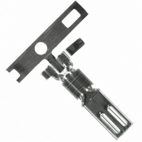
VL Crimp Disconnectable Crimp style connectors 6.2mm (.244") pitch This 6.2mm (.244") pitch wire-to-board connector is designed for circuits with high power requirements. CONNECTOR Features ––––––––––––––––––––––– • Housing lances for contact retention Since the contact retention lances are part of ...

Page 2

... L JST 6.2(.244) Cir- Model No. cuits VLP-03V 3 VLP-04V 4 VLP-06V 6 Material Nylon 66, UL94V-0, white 15 Model No. SVF-42T-P2.0 SVF-61T-P2.0 SVF-81T-P2.0 3.7 Note: SVF-42T-P2.0 is not TU ¨ V approved. (4 circuits) 13.4(.528 6.2(.244) Q´ty / bag 500 500 500 Applicable wire Q´ty / Insulation O.D. reel ...

Page 3

Retainer –––––––––––––––––––––––––––––––––––––––––––––––––––––––––––––––– (4 circuits) 11.4(.449) (3, 6 circuits) 17.6(.693) Shrouded header ––––––––––––––––––––––––––––––––––––––––––––––––––––––––– (3 circuits) 19.6(.772) 1.8 (.071) (.063) 3 6.2(.244) (.142) 12.4(.488) Dimensions mm(in.) Cir- Model No. cuits B03P-VL 4 B04P-VL 6.2(.244) 6 B06P-VL 12.4(.488) ...

Page 4

VL CONNECTOR Contact position location numbers –––––––––––––––––––––––––––––––––––––––––– (3 circuits board layout (viewed from soldering side) (3 circuits) ± 12.4 0.1 3.6 ± (.488 .004)dia. (.142) ± 6.20 0.05 ± (.244 .002)dia. ± 2.1 0.05 ± (.083 ...

Related keywords