AEO04B48N-6L Emerson Network Power, AEO04B48N-6L Datasheet - Page 26
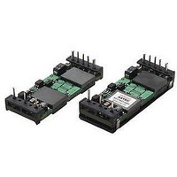
AEO04B48N-6L
Manufacturer Part Number
AEO04B48N-6L
Description
DC/DC Converter
Manufacturer
Emerson Network Power
Specifications of AEO04B48N-6L
Dc / Dc Converter O/p Type
Fixed
No. Of Outputs
1
Input Voltage
36V To 75V
Power Rating
48W
Output Voltage
12V
Output Current
4A
Approval Bodies
CUL, TUV, UL
Supply Voltage
48V
Product
Isolated
Output Power
48 W
Input Voltage Range
36 V to 75 V
Input Voltage (nominal)
48 V
Number Of Outputs
1
Output Voltage (channel 1)
12 V
Output Current (channel 1)
4 A
Isolation Voltage
1.5 KV
Package / Case Size
Eighth Brick
Lead Free Status / RoHS Status
Lead free / RoHS Compliant
Lead Free Status / RoHS Status
Lead free / RoHS Compliant


SOLDERING CONSIDERATIONS
The AEO (baseplate) series converters are compatible
with standard wave soldering techniques. When wave
soldering, the converter pins should be preheated for
20-30 seconds at 110°C and wave soldered at 260°C
for less than 10 seconds.
When hand soldering, the iron temperature should be
maintained at 425°C and applied to the converter pins
for less than 5 seconds. Longer exposure can cause
internal damage to the converter. Cleaning can be
performed with cleaning solvent IPA or with water.
For SMT terminated modules, refer to Figure 64 for
the recommended reflow profile.
TABLE 2: PART NUMBERING SCHEME
Note: 1) For Through Hole termination:
MODEL: AEO_ALO04/12/20/25x48 SERIES
AUGUST 25, 2005 - REVISION G
A
Please call 1-888-41-ASTEC for further inquiries
or visit us at
L = Open frame
E = Baseplate
CONSTRUCTION
w
www.astecpower.com
O
O/P CURRENT
04 = 4A
12 = 12A
20 = 20A
20 = 20A
25 = 25A
25 = 25A
25 = 25A
AEO_ALO04/12/20/25x48 Series
xx
Technical Reference Notes
- Std pin length is 5mm nominal (min: 0.189 [4.8]; max: 0.205 [5.2] / in [mm])
- “-6” option is 3.7mm nominal (min: 0.137 [3.5]; max: 0.152 [3.9] / in [mm])
- Pins 4&8 diameter: ∅ = 0.062 [1.57], others: ∅ = 0.04 [1.0] (6X)
(Single Output 8
O/P VOLTAGE
B =12V
A =5V
F =3.3V
G =2.5V
Y =1.8V
M =1.5V
K =1.2V
y
240
220
200
180
160
140
120
100
80
60
40
20
0
Figure 64. Recommended reflow profile for SMT modules.
0
48
Vin
th
Brick)
183°C
110°C
30
RECOMMENDED REFLOW PROFILE
N = Negative
Blank = Positive
< 4°C /sec
SLOPE
60
Enable
N
90
PRE-HEAT ZONE
PEAK TEMPERATURE
120 - 180 sec
200°C - 230°C
120
TIME (seconds)
-
150
6 = 3.7mm
blank = 5mm
default
PIN LENGTH
6
180
210
REFLOW
< 80 sec
S = SMT Termination
Blank = thru-hole
SHEET 26 OF 26
ZONE
TERMINATION
240
S
270
300
Related parts for AEO04B48N-6L
Image
Part Number
Description
Manufacturer
Datasheet
Request
R

Part Number:
Description:
DC/DC Converter
Manufacturer:
Emerson Network Power
Datasheet:
Part Number:
Description:
DC/DC Converter
Manufacturer:
Emerson Network Power
Datasheet:

Part Number:
Description:
48W, 36V-75Vin, Single, 12.0V@4A, 1/8 Brick B/plate, 93% Eff, Pos, 3.7mm TH, RoHS 6
Manufacturer:
Emerson Network Power
Datasheet:
Part Number:
Description:
48W, 36V-75Vin, Single, 12.0V@4A, 1/8 Brick B/plate, 93% Eff, Pos, 5mm TH, RoHS 6
Manufacturer:
Emerson Network Power
Datasheet:

Part Number:
Description:
AC/DC Front end 12Vo 36A 12Vsb Standard Airflow
Manufacturer:
Emerson Network Power

Part Number:
Description:
POWER SUPPLY SGL 5VOUT 40W 3X5"
Manufacturer:
Emerson Network Power
Datasheet:

Part Number:
Description:
POWER SUPPLY DIN 24VDC 10A
Manufacturer:
Emerson Network Power
Datasheet:

Part Number:
Description:
POWER SUPPLY SGL 48VOUT 40W 3X5"
Manufacturer:
Emerson Network Power
Datasheet:

Part Number:
Description:
POWER SUP MED&ITE 48V 45W 2"X4"
Manufacturer:
Emerson Network Power
Datasheet:

Part Number:
Description:
POWER SUPPLY 60W 12V OUT
Manufacturer:
Emerson Network Power
Datasheet:

Part Number:
Description:
POWER SUPPLY 60W 48V OUT
Manufacturer:
Emerson Network Power
Datasheet:

Part Number:
Description:
POWER SUPPLY 60W 15V OUT
Manufacturer:
Emerson Network Power
Datasheet:

Part Number:
Description:
POWER SUPPLY TRPL 3.3/5/12V 40W
Manufacturer:
Emerson Network Power
Datasheet:

Part Number:
Description:
POWER SUPPLY SWITCHER 24V 40W
Manufacturer:
Emerson Network Power
Datasheet:

Part Number:
Description:
Linear & Switching Power Supplies 24V output 25W 2A Medical &Non-Medical
Manufacturer:
Emerson Network Power
Datasheet: