13100122 SCHROFF, 13100122 Datasheet - Page 3
13100122
Manufacturer Part Number
13100122
Description
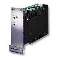
PSU, RACK MODULE, 100W, 5V, +/-12V
Manufacturer
SCHROFF
Datasheet
1.13100123.pdf
(5 pages)
Specifications of 13100122
Power Supply Type
Switch Mode
Power Supply Output Type
Fixed
No. Of Output Channels
3
Input Frequency
60Hz
Output Voltage
5V
Output Current
8A
Power Rating
100W
Input Voltage
90VAC To 254VAC
No. Of Outputs
3
Rohs Compliant
Yes
Lead Free Status / RoHS Status
Lead free / RoHS Compliant


Serienschaltung V
Series operation for ± 12 V
Branchement en série ± 12 V
Serienschaltung V
Series operation for +24 V
Branchement en série +24 V
Einstellung von V
Adjustment from V
Reglage V
Signal „Output OK“ V
Output V
5 V
2
1
/V
3
V
2
2
2
/V
2
2
/V
/V
/V
3
3
3
3
1
für ± 12 V
für + 24 V
4,5
V
U
± 0,2
3
s
DIJM0089
DIJM0090
DIJM0088
DIJM0033
V
Leistungsbegrenzung
Zum Schutz des Gerätes muß der
Anwender bei Temperaturen > 50 °C
die Ausgangsleistung reduzieren.
Strombegrenzung
Die Geräte sind für Dauerkurzschluß
ausgelegt. Der Ausgangsstrom wird
begrenzt. Bei einem Kurzschluß am
Ausgang, schaltet der Ausgang ab und
versucht immer wieder neu zu starten.
Steht eine Überlast längere Zeit an,
schaltet das Netzgerät ab. Wiederan-
lauf durch Netz aus-/ einschalten.
Wird die Ausgangsspannung vom
Anwender erhöht, muß er sicherstellen,
daß der maximale Ausgangsstrom um
den gleichen Faktor verringert wird.
Beispiel: U
Überspannungsschutz (OVP)
Der OVP vom Ausgang 1 ist über eine
zweite Regelschleife realisiert. Schwel-
len siehe Spezifikationen.
Bei einem Fehler der OVP-Schaltung
legieren die internen Schutzdioden
durch und müssen werkseitig ausge-
tauscht werden.
Serienschaltung von V
Sehen Sie am Ausgang externe Invers-
dioden vor. Bei Serienschaltung kön-
nen am Ausgang berührungs-
gefährliche Spannungen auftreten:
SELV-Spannung nur bis 60 V
Die Ausgänge V
vanisch getrennt.
Parallelschaltung
Die Parallelschaltung der Nebenaus-
gänge V
Ausgangsspannung V
Die Einstellung der Nebenausgangs-
spannung darf nur durch Fachpersonal
vorgenommen werden. Es darf nur ein
vollkommen isolierter Schraubendreher
verwendet werden. Position der Potis
siehe „Einstellung von V
Damit die Ausgangsspannung -V
handen ist, muss Pin 18 mit Pin 20
gebrückt sein.
Netzspannung
Die Netzgeräte haben einen Weitbe-
reichseingang (90 V
Output OK Signal
Das Signal „Output OK“ zeigt an, ob die
Ausgangsspannung V
(siehe Diagramm Signal “Output OK“).
Garantiebedingungen
Leistungsdauer
Für dieses Produkt leisten wir 2 Jahre Garantie.
Der Anspruch beginnt mit dem Tage der
Auslieferung.
Umfang der Mängelbeseitigung
Innerhalb der Garantiezeit beseitigen wir kostenlos
alle Funktionsfehler am Produkt, die auf mangelhafte
Ausführung bzw. Materialfehler zurückzuführen sind.
Weitergehende Ansprüche – insbesondere für
Folgeschäden – sind ausgeschlossen.
Garantieausschluß
Schäden und Funktionsstörungen verursacht durch
Nichtbeachten unserer Bedienungsanleitung sowie
Fall, Stoß, Verschmutzung oder sonstige unsach-
gemäße Behandlung fallen nicht unter die Garantie-
leistung.
Die Garantie erlischt, wenn das Produkt von
unbefugter Seite geöffnet wurde. Eingriffe erfolgt
sind oder die Seriennummer am Produkt verändert
oder unkenntlich gemacht wurde.
Abwicklung des Garantieanspruches
Das vorliegende Produkt wurde sorgfältig geprüft
und eingestellt.
Bei berechtigten Beanstandungen schicken Sie uns
das Produkt bitte zurück. Zur Erhaltung Ihres
Garantieanspruches beachten Sie bitte folgendes:
Legen Sie eine möglichst genaue Beschreibung
des Defektes bei.
Das Produkt ist im Original-Karton oder gleich-
wertiger Verpackung einzusenden und zwar
versichert und portofrei.
2
und V
DC
+ 10 % => I
3
2
ist nicht vorgesehen.
und V
AC
1
– 254 V
vorhanden ist
3
2
DC
/ V
sind nicht gal-
2
- 10 %.
2
3
/V
/V
DC
“.
AC
3
.
3
3
).
vor-
Output power limiting
In order to protect the unit, the user must
reduce the output currents at
temperatures > 50 °C.
Current limiting
The power supply features short-circuit
protection. The output current is limited .
If the overload persists, the output
voltage switches off, then keeps trying
to reset. If it persists for a long while, the
power supply switches off. For restart
switching the power supply on/off.
If the output voltage is increased by the
user, the maximum output current must
be reduced by the same factor.
Example: V
Over-voltage protection (OVP)
The OVP of output 1 is realized by
means of an additional loop. For
thresholds, please refer to the
specifications.
If there is a fault in the OVP circuit the
internal protection diodes are short-
circuited and must be replaced at the
factory.
Series operation of V
External inverse diodes should be used
at the output. If the current limiting is
triggered in a unit the load should be
removed briefly. Dangerous voltages
may occur at the output with series
operation:
SELV voltage only up to 60 V
The unit outputs V
galvanically isolated.
Parallel operation
Parallel connection of the V
outputs is not planed.
Output voltage V
The unit output voltage may be set by
qualified personnel only. It is only
allowed to use a complete isolated srew
driver. The position of the potentiometer
see “Adjustment from V
That the output -V
must be connected to Pin 20.
Mains/line voltage
The power supplies have a broad
range input (90 V
Output OK Signal
The Output OK Signal is on if there is an
existing output voltage V
Signal “Output OK“).
Warranty conditions
Duration
This product has a warranty of 2 years.
The warranty begins on the day of delivery
Cover of defects
Within the warranty period Schroff will repair free of
charge any faulty functioning of the product
resulting from faulty design or defective material.
All other claims under the warranty are excluded, in
particular consequential damage.
Warranty exclusion
The warranty does not cover damage or functional
defects caused by non-adherence to the
Company´s operating instructions or such caused
by dropping, knocking, contamination or other
untoward handling. The warranty is invalidated if
the product is opened by unauthorized personnel,
tampered with or the serial number on the product
has been changed or rendered illegible.
Claims under warranty
This product has been carefully checked. If you
have a valid claim, please return the product to
SCHROFF. In order to make a claim under the
warranty, ensure that the following is carried out:
Include a detailed description of the fault.
The product should be returned in the original
carton or similar packaging, insured and
post paid.
DC
+ 10 % => I
AC
3
2
is working Pin 18
and V
– 254 V
2
/V
2
3
1
/ V
2
(see diagram
DC
3
/V
3
are not
2
AC
“.
- 10 %.
DC
and V
3
).
.
3
Limitation de puissance
Afin de protéger l’alimentation, l’utilisateur
doit réduire le courant de sortie si la
température est > 50 °C.
Limitation de courant
Les alimentations sont conçues pour
pouvoir supporter un court-circuit
permanent. Le courant de sortie est limité.
Si le court-circuit persiste, la tension de
sortie est coupée et essaye de redémarrer.
Si la surcharge persiste l’alimentation se
coupe. Pour redémarrer couper brièvement
le courant secteur.
Si l’utilisateur accroît la tension de sortie, il
doit veiller à réduire le courant maximal de
sortie dans la même proportion.
Exemple: U
Protection contre les surtensions
L’OVP de la sortie 1 est réalisée par une
régulation séparée. Voir la courbe des
caractéristiques techniques pour les limites.
Dans le cas d’une erreur dans le circuit
OVP, les diodes internes de sécurité sont
mises en court circuit et doivent être
remplacées à l’usine.
Branchement en série de V
Il faut prévoir des diodes de protection
contre les inversions de polarité. Lorsque
l’un des appareils déclenche en limitation
de courant, il faut déconnecter la charge
pendant un court moment. Lors d’une mise
en série, des tensions dangereuses
peuvent apparaître à la sortie:
tension SELV uniquement jusqu’à 60 V
Les sorties des alimentations V
sont pas isolées galvaniquement.
Branchement en parallèle
Le branchement en parellèle des sorties V
et V
Tensions de sortie V
Le réglage des tensions de sortie doit être
fait par du personnel qualifié. L’utilisation
d’un tournevis complètement isolé est
impératif. Pour la position des
potentiomètres voir „Reglage V
Pour qu’il y ait la tension -V
et 20 doivent être courcircuités.
Adaptation de la tension secteur
L´alimentation dispose d´une plage d´ent-
rée secteur étendue. Elle s´adapte auto-
matiquement à la tension secteur
(90 V
OK Signal Output
L
non de la tension de sortie V
Signal “Output OK“
Garantie
Garantie contractuelle
Les conditions d‘applications de la garantie, et en
particulier la durée, l‘étendue et les cas d‘exclusion,
figurent dans nos conditions générales de ventes,
paragraphe 11 „Garantie contractuelle“.
Application de la garantie
Cette alimentation a été soigneusement contrôlée en
usine. En cas de réclamations, veuillez nous la
retourner accompagnée d‘une description la plus
précise possible du défaut constaté, et d‘une copie du
bon de livraison ou de la facture. Le produit doit nous
être retourné dans son emballage d‘origine port
assuré et payé.
Schroff n‘assume aucune responsabilité pour des
appareils non assurés et endommagés pendant le
transport.
e signal Output OK indique la présence ou
3
AC
n’est pas prévu.
– 254 V
DC
+ 10 % => I
AC
).
).
2
DC
/V
3
les broches 18
1
3
- 10 %.
(voir schéma
2
2
/ V
et V
2
/V
3
“.
3
3
ne
DC
.
2
Related parts for 13100122
Image
Part Number
Description
Manufacturer
Datasheet
Request
R

Part Number:
Description:
PSU, RACK MODULE, 50W, 5V
Manufacturer:
SCHROFF
Datasheet:
Part Number:
Description:
PSU, RACK MODULE, 50W, 12V
Manufacturer:
SCHROFF
Datasheet:

Part Number:
Description:
PSU, RACK MODULE, 100W, 5V, +/-15V
Manufacturer:
SCHROFF
Datasheet:
Part Number:
Description:
PSU, RACK MODULE, 50W, 24V
Manufacturer:
SCHROFF
Datasheet:

Part Number:
Description:
PSU, RACK MODULE, 100W, 12V
Manufacturer:
SCHROFF
Datasheet:
Part Number:
Description:
PSU, RACK MODULE, 100W, 24V
Manufacturer:
SCHROFF
Datasheet:
Part Number:
Description:
PSU, RACK MODULE, 100W, 16-30V
Manufacturer:
SCHROFF
Datasheet:

Part Number:
Description:
PSU, RACK MODULE, 42W, 5V
Manufacturer:
SCHROFF
Datasheet:

Part Number:
Description:
CONN JACK 1/4" 3-COND IN-LINE
Manufacturer:
Switchcraft Inc.
Datasheet:


Part Number:
Description:
BATTERY HOLDER, 2/3A, PCB
Manufacturer:
Keystone Electronics
Datasheet:

Part Number:
Description:
Accessories, 19 blank panel, aluminium
Manufacturer:
Schroff GmbH