UQQ-5/20-Q48P-C Murata Power Solutions Inc, UQQ-5/20-Q48P-C Datasheet - Page 10
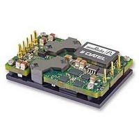
UQQ-5/20-Q48P-C
Manufacturer Part Number
UQQ-5/20-Q48P-C
Description
CONVERTER, DC/DC, WI, 100W, 5V
Manufacturer
Murata Power Solutions Inc
Series
UQQr
Datasheet
1.UQQ-3.325-Q12P-C.pdf
(14 pages)
Specifications of UQQ-5/20-Q48P-C
Output Type
Single
No. Of Output Channels
1
Input Voltage
18V To 75V
Power Rating
100W
Output Voltage
5V
Output Current
20A
Supply Voltage
48V
Dc / Dc Converter Case Style
Quarter Brick
Dc / Dc Converter O/p Type
Single
No. Of Outputs
1
Approval Bodies
EN / IEC / UL
Rohs Compliant
Yes
Product
Isolated
Output Power
100 W
Input Voltage Range
18 V to 75 V
Input Voltage (nominal)
48 V
Number Of Outputs
1
Output Voltage (channel 1)
5 V
Output Current (channel 1)
20 A
Isolation Voltage
2.25 KV
Package / Case Size
Quarter Brick
Lead Free Status / RoHS Status
Lead free / RoHS Compliant


Calculating Maximum Power Dissipation
To determine the maximum amount of internal power dissipation, find the
ambient temperature inside the enclosure and the airflow (in Linear Feet per
Minute – LFM) at the converter. Determine the expected heat dissipation
using the Efficiency curves and the converter Input Voltage. You should also
compensate for lower atmospheric pressure if your application altitude is
considerably above sea level.
The general proceedure is to compute the expected temperature rise of the
heatsink. If the heatsink exceeds +00°C. either increase the airflow and/or
reduce the power output. Start with this equation:
where “Ta” is the enclosure ambient air temperature and,
where “Ts” is the heatsink temperature and,
where “RQ [at airflow]” is a specific heat transfer thermal resistance (in
degrees Celsius per Watt) for a particular heat sink at a set airflow rate. We
have already estimated RQ [at airflow] in the equations above.
Note particularly that Ta is the air temperature inside the enclosure at the
heatsink, not the outside air temperature. Most enclosures have higher
internal temperatures, especially if the converter is “downwind” from other
heat-producing circuits. Note also that this “Pd” term is only the internal heat
dissipated inside the converter and not the total power output of the converter.
We can rearrange this equation to give an estimated temperature rise of the
heatsink as follows:
These model numbers are correct for the UQQ series.
www.cd4power.com
P O W E R E L E C T R O N I C S D I V I S I O N
Heatsink Kit *
Model Number
HS-QB25-UVQ
HS-QB50-UVQ
HS-QB00-UVQ
* Kit includes heatsink, thermal pad and mounting hardware.
Internal Heat Dissipation [Pd in Watts] = (Ts – Ta)/RQ [at airflow] [6]
Ts = (Pd x RQ [at airflow]) + Ta [7]
Still Air (Natural convection)
thermal resistance
0.6°C/Watt
2°C/Watt
8°C/Watt
Heatsink height
0.25" (6.35mm)
0.50" (2.7mm)
.00" (25.4mm)
(see drawing)
Heat Sink Example
Assume an efficiency of 92% and power output of 00 Watts. Using equation
[4], Pd is about 8.7 Watts at an input voltage of 48 Volts. Using +30°C ambient
temperature inside the enclosure, we wish to limit the heat sink temperature
to +90°C maximum baseplate temperature to stay well away from thermal
shutdown. The +90°C. figure also allows some margin in case the ambient
climbs above +30°C or the input voltage varies, giving us less than 92%
efficiency. The heat sink and airflow combination must have the following
characteristics:
Since the ambient thermal resistance of the heatsink and pad is 2.5°C/W, we
need additional forced cooling to get us down to 6.9°C/W. Using a hypothetical
airflow constant of 0.005, we can rearrange equation [5] as follows:
or,
and, rearranging again,
62 LFM is the minumum airflow to keep the heatsink below +90°C. Increase
the airflow to several hundred LFM to reduce the heatsink temperature further
and improve life and reliability.
(2.54)
(Required Airflow, LFM) x (Airflow Constant) = RQ[Nat.Convection] /
RQ[at airflow] –
(Required Airflow, LFM) x (Airflow Constant) = 2.5/6.9 – = 0.8
8.7 W = (90-30) / RQ[airflow] or,
RQ[airflow] = 60/8.7 = 6.9°C/W
(Required Airflow, LFM) = 0.8/0.005 = 62 LFM
0.10
* UQQ SERIES HEATSINKS ARE AVAILABLE IN 3 HEIGHTS:
0.140 DIA. (3.56) (4 PLACES)
Wide Input Range Single Output DC/DC Converters
MATERIAL: BLACK ANODIZED ALUMINUM
0.25 (6.35), 0.50 (12.70) AND 1.00 (25.4)
Dimensions in inches (mm)
Optional Heatsink
(57.91)
(47.24)
1.860
2.28
D C / D C C O N V E R T E R S
UQQ Series
MDC_UQQ_A02
(26.16)
1.03
*
Page 0 of 4
(36.83)
1.45
Related parts for UQQ-5/20-Q48P-C
Image
Part Number
Description
Manufacturer
Datasheet
Request
R

Part Number:
Description:
CONV DC/DC 100W 20A 5V T/H
Manufacturer:
Murata Power Solutions Inc
Datasheet:

Part Number:
Description:
DC/DC Converter
Manufacturer:
Murata Power Solutions Inc
Datasheet:

Part Number:
Description:
DC/DC Converters & Regulators 48Vin 5Vout 20A neg polarity TH
Manufacturer:
Murata Power Solutions Inc
Datasheet:
Part Number:
Description:
CONV DC/DC 85W 17A 5V T/H
Manufacturer:
Murata Power Solutions Inc
Datasheet:
Part Number:
Description:
DC/DC TH 17A 12-5V Q-brick
Manufacturer:
Murata Power Solutions Inc

Part Number:
Description:
DC/DC Converter
Manufacturer:
Murata Power Solutions Inc
Datasheet:

Part Number:
Description:
DC/DC TH 17A 12-5V Q-brick
Manufacturer:
Murata Power Solutions Inc
Part Number:
Description:
CONV DC/DC 82.5W 25A 3.3V T/H
Manufacturer:
Murata Power Solutions Inc
Datasheet:

Part Number:
Description:
CONV DC/DC 96W 8A 12V T/H
Manufacturer:
Murata Power Solutions Inc
Datasheet:
Part Number:
Description:
CONV DC/DC 96W 4A 24V T/H
Manufacturer:
Murata Power Solutions Inc
Datasheet:
Part Number:
Description:
CONV DC/DC 85W 17A 5V T/H
Manufacturer:
Murata Power Solutions Inc
Datasheet:

Part Number:
Description:
Transformers 5Vin 5Vout 200mA 4000Vdc 1:1.33 turn
Manufacturer:
Murata Power Solutions Inc
Datasheet:
Part Number:
Description:
POWER SUPPLY
Manufacturer:
Murata Power Solutions Inc
Datasheet:

Part Number:
Description:
DPM LED MINI 2VDC 3.5DIG LP RED
Manufacturer:
Murata Power Solutions Inc
Datasheet:

Part Number:
Description:
CONV DC/DC 1W 5VIN 5VOUT SIP SGL
Manufacturer:
Murata Power Solutions Inc
Datasheet: