DMS-40LCD-1/2-9-C Murata Power Solutions Inc, DMS-40LCD-1/2-9-C Datasheet - Page 5
DMS-40LCD-1/2-9-C
Manufacturer Part Number
DMS-40LCD-1/2-9-C
Description
DPM ±2/20V LCD 9V-Pwr
Manufacturer
Murata Power Solutions Inc
Datasheet
1.DMS-30-CP.pdf
(6 pages)
Specifications of DMS-40LCD-1/2-9-C
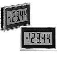
Display Type
4 - 1/2 Digit LCD
Lead Free Status / RoHS Status
Lead free / RoHS Compliant


APPLICATIONS
5. Process Control (4-to-20mA) Measurements: In many common
To calibrate the circuit of Figure 7, perform the following:
1. With 4mA applied, adjust the 50kΩ potentiometer (R2) to
2. With 20mA applied, adjust the gain-adjust potentiometer on
process-control applications, a 4-to-20mA current loop is used to
transmit information. Because DMS-40LCD meters have such high
input impedance, a simple shunt resistor across the meter’s input can
be used to convert the loop current to a voltage. See Figure 7. The
value of the shunt resistor is a function of the scaling requirements of
the particular application and can be calculated using the following
equation:
display a reading of "0000" (assuming that is the desired
reading).
the back of the meter to display a reading of "19999".
For different full scale readings, alter the value of R
accordingly.
Where:
Example: For a meter with a 2V full scale input (1.999 full
scale reading) and a desired full scale display reading of
1000 (with an input of 20mA), V
4-20mA
+
–
120 VAC
R
R
R
Figure 7. 4-to-20mA Current Loop Operation
AC to DC Converter
R1
Shunt
V
Shunt
Shunt
I
Fsr
Fsr
= R1 = V
= Full scale reading (in Volts)
= Relative full scale current (in Amps)
= 1.000V/(0.020 – 0.004)A
= 1.000V/0.016A = 62.5 Ohms
ANA COMM
50k
(–) IN LO
(+) IN HI
R2
(5V-Powered Models)
11
10
12
Fsr
/ I
+5V SUP
Fsr
Fsr
1
= 1.000 Volts
DMS-40LCD-0/1-5
RANGE
2
Shunt
3
5V RET
www.murata-ps.com/dpm
6. Power Supply Monitoring: A popular application for DATEL’s low-
power LCD meters is monitoring the supply voltage in battery-operated
portable equipment. Figure 8 demonstrates how a 9V-powered DMS-
40LCD can be used to monitor its own supply. The meter used is the
DMS-40LCD-0/1-9 confi gured for its ±2V input range (pin 2 connected
to pin 1). A three-resistor voltage divider is used to attenuate the bat-
tery voltage and also to satisfy the requirement that the input voltages
applied to pins 12 and 11 be at least 1.5 Volts above and below the
battery voltage applied to pins 1 (+BATTERY) and 3 (–BATTERY).
The divider should be designed so that 1/10th the battery voltage falls
across the inputs to the meter.
Therefore, the 9V battery voltage appears to the meter inputs as 0.9V.
With the decimal point moved to its DP2 position (pin 5 tied to pin 3),
the meter reads 9.000 Volts.
The circuit can be calibrated by fi rst measuring the actual battery volt-
age with another meter and then adjusting the gain-adjust potentiom-
eter on the back of the DMS-40LCD until a similar reading is obtained.
If possible, the resistors in the divider should be ±1% metal-fi lm types
with TCR’s less than 50ppm/°C.
4½ Digit, LCD Display Digital Panel Voltmeters
BATTERY
9V
(R1 + R2 + R3)
+BAT
1
R2
–
+
RANGE
DMS-40LCD-0/1-9
Figure 8. Power Supply Monitor
2
DMS-40LCD Series
(9V-Powered Models)
= 0.1
04/05/11 MPM_DMS40LCD.C04 Page 5 of 6
–BAT
3
email: sales@murata-ps.com
5
DP2
11
(+) IN HI
12
(–) IN LO
R1
45.3k
10.1k
R2
45.3k
R3
Related parts for DMS-40LCD-1/2-9-C
Image
Part Number
Description
Manufacturer
Datasheet
Request
R

Part Number:
Description:
DPM ±.2/2V LCD BakLite 9V-Pwr
Manufacturer:
Murata Power Solutions Inc
Datasheet:
Part Number:
Description:
DPM ±2/20V LCD BakLite 5V-Pwr
Manufacturer:
Murata Power Solutions Inc
Datasheet:
Part Number:
Description:
DPM ±20/200V LCD BkLite 5V-Pwr
Manufacturer:
Murata Power Solutions Inc
Datasheet:
Part Number:
Description:
DPM ±20/200V LCD BkLite 9V-Pwr
Manufacturer:
Murata Power Solutions Inc
Datasheet:

Part Number:
Description:
Voltage Meter
Manufacturer:
Murata Power Solutions Inc
Datasheet:

Part Number:
Description:
POWER OVER ETHERNET MODULE
Manufacturer:
Murata Power Solutions Inc
Datasheet:

Part Number:
Description:
POWER OVER ETHERNET MODULE
Manufacturer:
Murata Power Solutions Inc
Datasheet:

Part Number:
Description:
POWER OVER ETHERNET MODULE
Manufacturer:
Murata Power Solutions Inc
Datasheet:

Part Number:
Description:
POWER OVER ETHERNET MODULE
Manufacturer:
Murata Power Solutions Inc
Datasheet:

Part Number:
Description:
Power Inductors 2.2mH1.4A
Manufacturer:
Murata Power Solutions Inc
Datasheet:

Part Number:
Description:
Digital Panel Meters DMS-20 BezelAssembly Panel mount
Manufacturer:
Murata Power Solutions Inc
Datasheet:

Part Number:
Description:
DPM LED MINI 2VDC 3.5DIG LP RED
Manufacturer:
Murata Power Solutions Inc
Datasheet:

Part Number:
Description:
DPM LED 2VDC 4.5DIGIT GREEN
Manufacturer:
Murata Power Solutions Inc
Datasheet:

Part Number:
Description:
DPM LED 2VDC 3.5DIGIT LP RED
Manufacturer:
Murata Power Solutions Inc
Datasheet:

Part Number:
Description:
Transformers 5Vin 5Vout 200mA 4000Vdc 1:1.33 turn
Manufacturer:
Murata Power Solutions Inc
Datasheet: