DSD-40BCD-GS-C Murata Power Solutions Inc, DSD-40BCD-GS-C Datasheet - Page 2
DSD-40BCD-GS-C
Manufacturer Part Number
DSD-40BCD-GS-C
Description
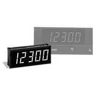
Slave Display 4.5 Dig Grn LED
Manufacturer
Murata Power Solutions Inc
Type
One-Piece LED Displaysr
Datasheet
1.DSD-40BCD-RS-C.pdf
(5 pages)
Specifications of DSD-40BCD-GS-C
Equipment Type
One-Piece LED Displays
Display Type
4 - 1/2 Digit LED
Lead Free Status / RoHS Status
Lead free / RoHS Compliant
Available stocks
Company
Part Number
Manufacturer
Quantity
Price


Functional Specifi cations
TA = +25°C and supply voltage = +5V, unless otherwise noted.
DSD-40BCD - RS-C
Accessories:
DMS-30-CP
DMS-BZL1-C
DMS-BZL2-C
A panel-mount retaining clip is supplied with each model.
Ordering Information
Control Inputs
BCD (pins I-L) and TEST (pin 2) Inputs:
Low-Level Input Voltage (V
Low-Level Input Current (I
High-Level Input Voltage (V
High-Level Input Current (I
Polarity Input (pin F):
Low-Level Input Voltage (V
Low-Level Input Current (I
High-Level Input Voltage (V
High-Level Input Current (I
Digit Drive Inputs (pins A-E):
Low-Level Input Voltage (V
Low-Level Input Current (I
High-Level Input Voltage (V
High-Level Input Current (I
DP1-DP4 Inputs (pins 4-6, 8):
Low-Level Input Voltage (V
Low-Level Input Current (I
High-Level Input Voltage (V
High-Level Input Current (I
Power Supply Requirements
Supply Voltage
Supply Current:
DSD-40BCD-GS
DSD-40BCD-RL
DSD-40BCD-RS
Panel cutout punch
DSD-40 bezel assembly
DSD-40 bezel assembly with sealing gasket
IL
IL
IL
IL
IH
IH
IH
IH
IL
IL
IL
IL
IH
IH
IH
IH
)
)
)
)
)
)
)
)
)
)
)
)
)
)
)
)
LED Color: GS = Standard Green
Min.
+4.75
+2.4
+4.5
+4.5
+4.5
–
–
–
–
–
–
–
–
–
–
–
–
–
–
–
Typ.
+5.00
RL = Low-Power Red
RS = Standard Red
+100
+35
+85
–
–
–
–
–
–
–
–
–
–
–
–
–
–
–
–
Max.
+5.25
+130
+110
+0.8
+0.8
+0.8
+0.8
0.05
0.05
0.05
+45
0.4
0.4
0.4
20
–
–
–
2
–
www.murata-ps.com/dpm
Units
Volts
Volts
Volts
Volts
Volts
Volts
Volts
Volts
Volts
mA
mA
mA
mA
mA
mA
mA
mA
mA
mA
mA
TECHNICAL NOTES
1. DSD-40BCD Operation (Please Refer to the Timing and Pinout Dia-
2. DSD-40BCD Timing Diagram (See Figure 2): The timing diagram de-
Miniature 4½ Digit, BCD Input, Slave LED Display
Display
Display Type and Size
LED Peak Wavelength (λ):
DSD-40BCD-GS
DSD-40BCD-RL
DSD-40BCD-RS
Physical/Environmental
Operating Temperature
Storage Temperature
Humidity (Non-condensing)
Case Material
Weight
BCD Inputs and Resultant Displays
0000 0001 0010 0011 0100 0101 0110 0111 1000 1001 1010 1011 1100 1101 1110 1111
grams for the Following Discussion): The DSD-40BCD display has fi ve
digits, labeled digit 1 (left-most digit or MSD) through digit 5 (right-
most digit or LSD), which are turned on by bringing their respective
DIGIT DRIVE inputs to a high logic level. The binary coded decimal data
(BCD) on pins I- L is decoded into the corresponding seven-segment
LED outputs necessary to display the numerals "0" through "9".
Since there are effectively fi ve digits and only one set of BCD data in-
puts, the DSD-40BCD's digits have their segments tied ("multiplexed")
together. The top segment, referred to as segment A, of digit 5 is
connected to the A segment of the other three digits (digit 1 has no A
segment). The remaining B, C, D, E, F and G segments are connected
to each other in the same fashion.
As an example of how the multiplexing scheme works, assume that
the BCD data inputs are 0001 (the BCD code for the decimal number
1) and also assume that the DIGIT DRIVE 3 input is high. Under these
conditions, the B and C segments of digits 1-5 will all be enabled.
However, only the digits whose DIGIT DRIVE inputs are high, in this
case only digit 3, will display the numeral "1". All the other digits will
be off. This example, while technically valid, will produce an extremely
bright "1" for digit 3. This will be explained in greater detail in the sec-
tion titled "Controlling the Display Brightness."
picts the required typical input conditions and timing relationships that
allow the user to access all 5 digits. The recommended display scan
rate is 100Hz. All 5 digits are scanned in 10ms, and each individual
digit is "on" for 2ms (20% duty cycle). The 100Hz fi gure is not critical;
it can go as low as 70Hz without any impact on display visibility.
The timing diagram shows the digits being scanned from left to
right (DIGIT 1 to DIGIT 5), but this order is not mandatory. Any drive
DSD-40BCD Series
10 Jan 2011 MPM_DSD-40BCD.B02 Page 2 of 5
Min.
–40
4½ Digit LED, 0.52"/13.2mm high
–
–
–
0
0
email: sales@murata-ps.com
1 ounce (28 grams)
565
630
635
Typ.
Polycarbonate
–
–
–
Max.
+70
+75
85
–
–
–
Units
nm
nm
nm
°C
°C
%
Related parts for DSD-40BCD-GS-C
Image
Part Number
Description
Manufacturer
Datasheet
Request
R

Part Number:
Description:
Slave Display 4.5 Dig Red LED
Manufacturer:
Murata Power Solutions Inc
Datasheet:

Part Number:
Description:
Slave LED Display
Manufacturer:
Murata Power Solutions Inc
Datasheet:

Part Number:
Description:
POWER OVER ETHERNET MODULE
Manufacturer:
Murata Power Solutions Inc
Datasheet:

Part Number:
Description:
POWER OVER ETHERNET MODULE
Manufacturer:
Murata Power Solutions Inc
Datasheet:

Part Number:
Description:
POWER OVER ETHERNET MODULE
Manufacturer:
Murata Power Solutions Inc
Datasheet:

Part Number:
Description:
POWER OVER ETHERNET MODULE
Manufacturer:
Murata Power Solutions Inc
Datasheet:

Part Number:
Description:
Power Inductors 2.2mH1.4A
Manufacturer:
Murata Power Solutions Inc
Datasheet:

Part Number:
Description:
Power Inductors 6.8uH 3.6A 20mOhm Toroidal SMT
Manufacturer:
Murata Power Solutions Inc
Datasheet:

Part Number:
Description:
Power Inductors Radial1.5mH 150mA
Manufacturer:
Murata Power Solutions Inc
Datasheet:
Part Number:
Description:
Power Inductors 680uH 2.2A 1.3MHz Radial PCB Mounting
Manufacturer:
Murata Power Solutions Inc
Datasheet:

Part Number:
Description:
Transformers 5Vin 5Vout 200mA 4000Vdc 1:1.33 turn
Manufacturer:
Murata Power Solutions Inc
Datasheet:

Part Number:
Description:
POWER SUPPLY
Manufacturer:
Murata Power Solutions Inc
Datasheet:

Part Number:
Description:
DPM LED MINI 2VDC 3.5DIG LP RED
Manufacturer:
Murata Power Solutions Inc
Datasheet:

Part Number:
Description:
CONV DC/DC 1W 5VIN 5VOUT SIP SGL
Manufacturer:
Murata Power Solutions Inc
Datasheet:

Part Number:
Description:
CONV DC/DC 1W 5VIN 3.3V SIP SGL
Manufacturer:
Murata Power Solutions Inc
Datasheet: