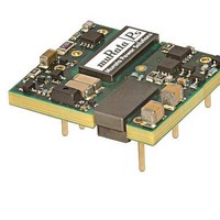
UEI15-150-Q48PM-C Murata Power Solutions Inc, UEI15-150-Q48PM-C Datasheet - Page 15

UEI15-150-Q48PM-C
Manufacturer Part Number
UEI15-150-Q48PM-C
Description
18-75Vin, 15Vout, 15W Positive Logic, SMT, RoHS
Manufacturer
Murata Power Solutions Inc
Series
UEI15r
Datasheet
1.UEI15-033-Q48NM-C.pdf
(16 pages)
Specifications of UEI15-150-Q48PM-C
Product
Isolated
Output Power
16.5 W
Input Voltage Range
18 V to 75 V
Input Voltage (nominal)
48 V
Number Of Outputs
1
Output Voltage (channel 1)
15 V
Output Current (channel 1)
1.1 A
Isolation Voltage
2.25 KV
Package / Case Size
0.96 in x 1.1 in x 0.32 in
Output Type
Isolated DC/DC Converters
Output Voltage
15 V
Lead Free Status / Rohs Status
Lead free / RoHS Compliant
disabled when the On/Off is grounded or brought to within a low voltage (see
Specifi cations) with respect to –V
brought to within a low voltage (see Specifi cations) with respect to –V
device is off (disabled) when the On/Off is left open or is pulled high to +15V
max. with respect to –V
signal current when brought low and withstand appropriate voltage when
brought high. Be aware too that there is a fi nite time in milliseconds (see
Specifi cations) between the time of On/Off Control activation and stable,
regulated output. This time will vary slightly with output load type and current
and input conditions.
put side ONLY. If you must control it from circuits in the output, use some form
of optoisolation to the On/Off Control. This latter condition is unlikely because
the device controlling the On/Off would have to remain powered on and not be
powered from the converter.
carefully observe the voltage levels, the preferred circuit is either an open
drain/open collector transistor, a switch or a relay (which can thereupon be
controlled by logic).
power voltage. Otherwise the converter may be permanently damaged.
To improve reliability, if you use a small signal transistor or other external
circuit to select the Remote On/Off control, make sure to return the LO side
directly to the –Vin power input on the DC/DC converter. To avoid ground
bounce errors, do not connect the On/Off return to a distant ground plane or
current-carrying bus. If necessary, run a separate small return wire directly to
the –Vin terminal. There is very little current (typically 1-5 mA) on the On/Off
control however, large current changes on a return ground plane or ground bus
can accidentally trigger the converter on or off. If possible, mount the On/Off
transistor or other control circuit adjacent to the converter.
Do not connect
control transistor
through remote
power bus
Negative-polarity devices are on (enabled) when the On/Off is grounded or
Dynamic control of the On/Off function should be able to sink appropriate
There are three CAUTIONs for the On/Off Control:
CAUTION: To retain full output circuit isolation, control the On/Off from the in-
CAUTION: While it is possible to control the On/Off with external logic if you
CAUTION: Do not apply voltages to the On/Off pin when there is no input
On/Off
Control
Transistor
Figure 8. On/Off Enable Control Ground Bounce Protection
IN
.
Ground plane or power return bus
IN
.
Preferred location
of On/Off control
adjacent to -Vin
terminal
Install separate
return wire for
On/Off control
with remote
transistor
DC/DC Converter
www.murata-ps.com
+ Vin
On/Off Enable
-Vin return
IN
. The
DC
Murata Power Solutions recommends the TH soldering specifi cations below when install-
ing these converters. These specifi cations vary depending on the solder type. Exceeding
these specifi cations may cause damage to the product. Your production environment may
differ; therefore please thoroughly review these guidelines with your process engineers.
The surface-mount refl ow solder profi le shown below is suitable for SAC305 type lead-
free solders. This graph should be used only as a guideline. Many other factors infl uence
the success of SMT refl ow soldering. Since your production environment may differ,
please thoroughly review these guidelines with your process engineers.
Maximum Preheat Temperature
Maximum Pot Temperature
Maximum Solder Dwell Time
Maximum Preheat Temperature
Maximum Pot Temperature
Maximum Solder Dwell Time
Isolated Wide Input Range 15-Watt DC/DC Converters
Figure 7. Driving the On/Off Control Pin (suggested circuit)
ON/OFF CONTROL
-INPUT
115° C.
270° C.
7 seconds
105° C.
250° C.
6 seconds
CONTROL
+ Vcc
Page 15 of 16


