P-312-CCT Cinch Connectors, P-312-CCT Datasheet - Page 4
P-312-CCT
Manufacturer Part Number
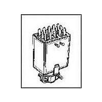
P-312-CCT
Description
CONN PLUG 12POS JONES SOLDER MNT
Manufacturer
Cinch Connectors
Series
300r
Type
Cable Plugr
Specifications of P-312-CCT
Connector Type
Plug, Jones
Contact Type
Tab
Number Of Positions
12
Pitch
0.156" (3.96mm)
Number Of Rows
3
Row Spacing
0.156" (3.96mm)
Mounting Type
Free Hanging (In-Line)
Cable Termination
Solder Eyelet
Wire Type
Discrete
Features
Cable Clamp
Contact Finish
Cadmium
Color
Black
Contact Termination
Solder
No. Of Contacts
12
No. Of Rows
2
Connector Mounting
Cable
Gender
Plug
Contact Material
Brass
Contact Plating
Cadmium
Agency Approvals
CSA, UL
Angle
Straight
Brand/series
300 Series
Current, Rating
10 A
Diameter
0.563 in.
Flammability Rating
UL94V-0
Length, Overall
1.286 "
Material, Contact
Brass
Material, Dielectric
Phenolic
Material, Hood
Thermoplastic
Material, Insulation
Phenolic
Number Of Contacts
12
Plating, Contact
Cadmium
Primary Type
Jones
Special Features
Polarized
Standards
UL Recognized File No: E170218 (UL 1977), E130965 (UL1863), CSA-LR31996
Temperature, Operating
0 to +105 °C
Termination
Solder
Thickness
0.974 in. ± 0.016 in.
Voltage, Rating
250 V
Width
1.286 in. ± 0.016 in.
Contact Gender
Pin
Rohs Compliant
No
Current Rating
10 A
Housing Material
Thermoplastic
Number Of Positions / Contacts
12
Voltage Rating
250 V
Lead Free Status / RoHS Status
Contains lead / RoHS non-compliant
Contact Finish Thickness
-
Fastening Type
-
For Use With
Cable to panel & cable to cable applications
Lead Free Status / Rohs Status
No
Other names
CJ112P
P-312-CCT-P
P312CCT-P
P-312-CCT-P
P312CCT-P


The unique construction of the CIN::APSE contact
provides superior mechanical and electrical performance.
It is constructed of randomly wound molybdenum wire that
is formed into a cyclindrical shape. Standard CIN::APSE
contact diameters are 0.020" and 0.040".
Mechanical
• Small form factor (0.020" diameter by 0.32" min. high)
• Low compression force (approx. 2.5 oz. min. per contact)
• Multiple beam structures
• Several points of contact per button
• Extremely lightweight
• Natural wiping action
Electrical
• Short signal path
• Very low inductance and resistance
• Signal integrity tested in the GHz range
The basic button contact
configuration consists of a single
button installed in our patented
“hourglass” design.
The hourglass cavity retains the
CIN::APSE contact securely.
Typically 0.003" protrudes from the
top and the bottom of the insulator.
CIN::APSE
High-Speed Interconnect Technology
THE BUTTON CONTACT
CIN::APSE APPLIED
®
Step 1:
Using alignment features,
position the CIN::APSE
connector between a LGA chip
package and PCB or two PCBs
that have matching footprints.
1-2
Typical CIN::APSE Applications
• LGA package I/O to PC board (IC packages,
• PC board to PC board (parallel processors,
• Flex circuit to PC board (rigid flex, harnessing)
• Flex circuit to ceramic (chip to harness)
multi-chip modules)
enhancement/mezzanine cards)
Step 2:
Add Z-Axis compression
and secure.
Call Toll Free: 1 (800) 323-9612
Related parts for P-312-CCT
Image
Part Number
Description
Manufacturer
Datasheet
Request
R

Part Number:
Description:
IC & Component Sockets DISC-MFG-1/01 12C CBL MNT PLUG
Manufacturer:
Cinch Connectors
Part Number:
Description:
IC & Component Sockets 12C PNL MNT PLUG
Manufacturer:
Cinch Connectors
Part Number:
Description:
IC & Component Sockets 12C PNL MNT PLUG
Manufacturer:
Cinch Connectors

Part Number:
Description:
CONN PLUG 3POS JONES SOLDER MNT
Manufacturer:
Cinch Connectors
Datasheet:
Part Number:
Description:
CONN PLUG 3POS W/BRACKET PNL MNT
Manufacturer:
Cinch Connectors
Datasheet: