VS-30CPQ035PBF Vishay, VS-30CPQ035PBF Datasheet - Page 2
VS-30CPQ035PBF
Manufacturer Part Number
VS-30CPQ035PBF
Description
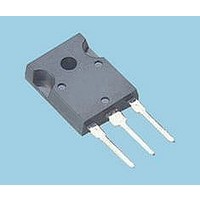
DIODE, SCHOTTKY, 2X15A, 35V, TO-247
Manufacturer
Vishay
Specifications of VS-30CPQ035PBF
Repetitive Reverse Voltage Vrrm Max
35V
Forward Current If(av)
15A
Forward Voltage Vf Max
500mV
Forward Surge Current Ifsm Max
1.02kA
Operating Temperature Range
-55°C To
Diode Type
Schottky
Product
Schottky Rectifiers
Peak Reverse Voltage
35 V
Forward Continuous Current
30 A
Max Surge Current
1020 A
Configuration
Dual Common Cathode
Forward Voltage Drop
0.68 V
Maximum Reverse Leakage Current
1750 uA
Mounting Style
Through Hole
Package / Case
TO-247AC
Lead Free Status / RoHS Status
Lead free / RoHS Compliant
Available stocks
Company
Part Number
Manufacturer
Quantity
Price
Company:

Part Number:
VS-30CPQ035PBF
Manufacturer:
ATMEL
Quantity:
2 000


Bulletin PD-20784 rev. A 11/06
Voltage Ratings
2
30CPQ035PbF, 30CPQ040PbF, 30CPQ045PbF
Absolute Maximum Ratings
Electrical Specifications
Thermal-Mechanical Specifications
I
I
E
I
V
I
C
L
dv/dt Max. Voltage Rate of Change
T
T
R
R
R
wt
T
V
V
F(AV)
FSM
AR
RM
S
J
stg
AS
FM
T
thJC
thJC
thCS
R
RWM
Part number
Max. DC Reverse Voltage (V)
Max. Working Peak Reverse Voltage (V)
Max. Average Forward Current
* See Fig. 5
Max. Peak One Cycle Non-Repetitive
Surge Current (Per Leg) * See Fig. 7
Non-Repetitive Avalanche Energy
(Per Leg)
Repetitive Avalanche Current
(Per Leg)
Max. Forward Voltage Drop
(Per Leg) * See Fig. 1
Max. Reverse Leakage Current
(Per Leg) * See Fig. 2
Max. Junction Capacitance (Per Leg)
Typical Series Inductance (Per Leg)
Parameters
Max. Junction Temperature Range
Max. Storage Temperature Range
Max. Thermal Resistance Junction
to Case (Per Leg)
Max. Thermal Resistance Junction
to Case (Per Package)
Typical Thermal Resistance, Case
to Heatsink
Approximate Weight
Mounting Torque
Case Style
Device Marking
Parameters
Parameters
(1)
(1)
Min.
Max.
30CPQ... Units
30CPQ... Units
TO-247AC(TO-3P) JEDEC
30CPQ... Units
-55 to 150
-55 to 150
6 (0.21)
12 (10)
10000
1020
0.54
0.68
0.50
0.64
1.75
2.20
1.10
0.24
6 (5)
265
900
7.5
30CPQ035
30CPQ040
30CPQ045
30
20
70
3
Kg-cm
(Ibf-in)
g (oz.)
30CPQ035PbF 30CPQ040PbF
°C/W DC operation
°C/W DC operation
°C/W Mounting surface , smooth and greased
V/ μs (Rated V
mA
mA
mJ
nH
pF
°C
°C
A
A
A
V
V
V
V
50% duty cycle @ T
5μs Sine or 3μs Rect. pulse
10ms Sine or 6ms Rect. pulse
T
Current decaying linearly to zero in 1 μsec
Frequency limited by T
@ 15A
@ 30A
@ 15A
@ 30A
T
T
V
Measured lead to lead 5mm from package body
Non-lubricated threads
35
J
J
J
R
= 25 °C, I
= 25 °C
= 125 °C
= 5V
DC
R
)
(test signal range 100Khz to 1Mhz) 25°C
Conditions
Conditions
AS
Conditions
= 3 Amps, L = 4.4 mH
(1) Pulse Width < 300μs, Duty Cycle <2%
V
T
T
J
J
R
* See Fig. 4
= 25 °C
= 125 °C
C
= rated V
= 124 °C, rectangular wave form
40
J
max. V
R
A
Following any rated
load condition and with
rated V
= 1.5 x V
30CPQ045PbF
RRM
www.irf.com
R
applied
typical
45
Related parts for VS-30CPQ035PBF
Image
Part Number
Description
Manufacturer
Datasheet
Request
R


Part Number:
Description:
357-036-542-201 CARDEDGE 36POS DL .156 BLK LOPRO
Manufacturer:
Vishay
Datasheet:
Part Number:
Description:
357-036-542-201 CARDEDGE 36POS DL .156 BLK LOPRO
Manufacturer:
Vishay
Datasheet:
Part Number:
Description:
357-036-542-201 CARDEDGE 36POS DL .156 BLK LOPRO
Manufacturer:
Vishay
Datasheet:
Part Number:
Description:
357-036-542-201 CARDEDGE 36POS DL .156 BLK LOPRO
Manufacturer:
Vishay
Datasheet:
Part Number:
Description:
357-036-542-201 CARDEDGE 36POS DL .156 BLK LOPRO
Manufacturer:
Vishay
Datasheet:
Part Number:
Description:
357-036-542-201 CARDEDGE 36POS DL .156 BLK LOPRO
Manufacturer:
Vishay
Datasheet:
Part Number:
Description:
357-036-542-201 CARDEDGE 36POS DL .156 BLK LOPRO
Manufacturer:
Vishay
Datasheet:
Part Number:
Description:
357-036-542-201 CARDEDGE 36POS DL .156 BLK LOPRO
Manufacturer:
Vishay
Datasheet:
Part Number:
Description:
357-036-542-201 CARDEDGE 36POS DL .156 BLK LOPRO
Manufacturer:
Vishay
Datasheet:
Part Number:
Description:
357-036-542-201 CARDEDGE 36POS DL .156 BLK LOPRO
Manufacturer:
Vishay
Datasheet:
Part Number:
Description:
357-036-542-201 CARDEDGE 36POS DL .156 BLK LOPRO
Manufacturer:
Vishay
Datasheet:
Part Number:
Description:
357-036-542-201 CARDEDGE 36POS DL .156 BLK LOPRO
Manufacturer:
Vishay
Datasheet:
Part Number:
Description:
357-036-542-201 CARDEDGE 36POS DL .156 BLK LOPRO
Manufacturer:
Vishay
Datasheet:
Part Number:
Description:
357-036-542-201 CARDEDGE 36POS DL .156 BLK LOPRO
Manufacturer:
Vishay
Datasheet: