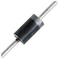
1N4151-TAP Vishay, 1N4151-TAP Datasheet - Page 2

1N4151-TAP
Manufacturer Part Number
1N4151-TAP
Description
SWITCHING DIODE, 75V, 150mA, DO-35
Manufacturer
Vishay
Datasheet
1.1N4151TAP.pdf
(4 pages)
Specifications of 1N4151-TAP
Diode Type
Small Signal
Forward Current If(av)
150mA
Repetitive Reverse Voltage Vrrm Max
75V
Forward Voltage Vf Max
1V
Reverse Recovery Time Trr Max
4ns
Forward Surge Current Ifsm Max
2A
Lead Free Status / RoHS Status
Lead free / RoHS Compliant
1N4151
Vishay Semiconductors
Electrical Characteristics
T
Typical Characteristics
T
www.vishay.com
2
Forward voltage
Reverse current
Breakdown voltage
Diode capacitance
Reverse recovery time
amb
amb
94 9151
Figure 1. Reverse Current vs. Junction Temperature
= 25 °C, unless otherwise specified
= 25 °C, unless otherwise specified
94 9152
1000
Figure 2. Forward Current vs. Forward Voltage
0.01
100
100
0.1
0.1
10
Parameter
10
1
1
0
0
Scattering Limit
T = 100 °C
0.4
T
40
j
j
V - Forward Voltage (V)
- Junction Temperature (°C)
F
DiodesAmericas@vishay.com, DiodesAsia@vishay.com,
0.8
80
T = 25 °C
For technical questions within your region, please contact one of the following:
j
1.2
120
I
F
i
R
V
= I
I
F
= 0.1 x I
R
V
V
= 10 mA, V
R
R
= 50 V, T
R
Test condition
V
= 10 mA, i
1.6
160
= 50 V
= 0, f = 1 MHz,
I
V
HF
F
I
R
R
= 50 mA
= 5 µA
= 50 mV
= 50 V
R
, R
2.0
j
200
= 150 °C
L
R
R
= 100 Ω
= 6 V,
= 1 mA
Symbol
V
C
V
I
I
(BR)
t
t
R
R
rr
rr
F
D
94 9153
Figure 3. Diode Capacitance vs. Reverse Voltage
3.0
2.5
2.0
1.5
1.0
0.5
0
DiodesEurope@vishay.com
0.1
Min.
75
V
R
- Reverse Voltage (V)
1
Typ.
880
14
T
f = 1 MHz
j
= 25 °C
10
Document Number 85523
Max.
1000
50
50
2
4
2
Rev. 1.8, 17-Aug-10
100
Unit
mV
nA
µA
pF
ns
ns
V


