VS-25RIA120 Vishay, VS-25RIA120 Datasheet - Page 3
VS-25RIA120
Manufacturer Part Number
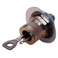
VS-25RIA120
Description
SCR THYRISTOR, 25A, 1.2KV, TO-208AA
Manufacturer
Vishay
Datasheet
1.VS-25RIA120.pdf
(9 pages)
Specifications of VS-25RIA120
Peak Repetitive Off-state Voltage, Vdrm
1.2kV
Gate Trigger Current Max, Igt
60mA
Current It Av
25A
On State Rms Current It(rms)
40A
Peak Non Rep Surge Current Itsm 50hz
440A
Lead Free Status / RoHS Status
Lead free / RoHS Compliant
Available stocks
Company
Part Number
Manufacturer
Quantity
Price


Blocking
(**) Available with: dv/dt = 1000V/μs, to complete code add S90 i.e. 25RIA160S90.
Switching
(*) t
Triggering
www.irf.com
dv/dt
di/dt
t
t
t
P
P
I
-V
I
V
I
V
gt
rr
q
GM
GT
GD
GM
G(AV)
GT
GD
q
GM
= 10μsup to 600V, t
Parameter
Parameter
Parameter
Max. rate of rise of turned-on
current
V
Typical turn-on time
Typical reverse recovery time
Typical turn-off time
Maximum peak gate power
Maximum average gate power
Max. peak positive gate current
Maximum peak negative
gate voltage
DC gate current required
to trigger
DC gate voltage required
to trigger
DC gate current not to trigger
DC gate voltage not to trigger
Max. critical rate of rise of
off-state voltage
DRM
≤ 800V
q
V
180
V
V
= 30μs up to 1600V available on special request.
DRM
DRM
DRM
≤ 600V
≤ 1000V
≤ 1600V
25RIA
25RIA
25RIA
300 (*)
200
110
100
160
150
0.9
8.0
2.0
1.5
3.0
2.0
1.0
2.0
10
90
60
35
0.2
4
I
TM
= (2x rated di/dt) A
Units Conditions
Units Conditions
A/μs
Units Conditions
V/μs
μs
mA
mA
W
A
V
V
V
V
T
Gate pulse = 20V, 15Ω, t
T
T
I
T
di/dt = -10A/μs, dv/dt = 20V/μs linear to
67% V
T
T
T
T
T
T
T
T
T
T
T
T
T
V
at = rated V
TM
J
J
J
J
J
J
J
J
J
J
J
J
J
J
J
J
J
DRM
= 25°C,
= T
= T
= T
= T
= T
= T
= T
= T
= - 65°C
= 25°C
= 125°C
= - 65°C
= 25°C
= 125°C
= T
= T
= I
= rated value
J
J
J
T(AV)
J
J
J
J
J
J
J
DRM
max., I
max., V
max.,
max. linear to 100% rated V
max. linear to 67% rated V
max.
max.
max.
max., V
max.
, gate bias 0V-100W
, t
DRM
p
TM
> 200μs, di/dt = -10A/μs
/V
DM
DRM
Max. required gate trigger current/
voltage are the lowest value which
will trigger all units 6V anode-to-
cathode applied
RRM
= I
= rated V
T(AV)
= rated value
, T
Bulletin I2402 rev. C 05/06
Max. gate current/ voltage not to
trigger is the max. value which
will not trigger any unit with rated
V
J
DRM
, t
= 125°C
p
p
= 6μs, t
> 200μs, V
anode-to-cathode applied
DRM
25RIA Series
r
DRM
= 0.1μs max.
DRM
R
= 100V,
3
Related parts for VS-25RIA120
Image
Part Number
Description
Manufacturer
Datasheet
Request
R

Part Number:
Description:
SCR Modules 2000 Volt 1473 Amp
Manufacturer:
Vishay Semiconductors
Datasheet:
Part Number:
Description:
SCR Modules 1650 Amp 2000 Volt 3080 Amp IT(RMS)
Manufacturer:
Vishay Semiconductors
Datasheet:

Part Number:
Description:
SCHOTTKY RECTIFIER, 1A, 30V, SMB
Manufacturer:
Vishay
Datasheet:

Part Number:
Description:
SCHOTTKY RECTIFIER, 1.1A, 30V, DO-204AL
Manufacturer:
Vishay
Datasheet:
Part Number:
Description:
SCHOTTKY RECTIFIER, 1.1A, 40V, DO-204AL
Manufacturer:
Vishay
Datasheet:

Part Number:
Description:
SCHOTTKY RECTIFIER, 1.1A, 50V, DO-204AL
Manufacturer:
Vishay
Datasheet:
Part Number:
Description:
SCHOTTKY RECTIFIER, 1.1A, 60V, DO-204AL
Manufacturer:
Vishay
Datasheet:

Part Number:
Description:
SCHOTTKY RECTIFIER, 3A, 40V, SMA
Manufacturer:
Vishay
Datasheet:
Part Number:
Description:
SCHOTTKY RECTIFIER, 2A, 30V, SMB
Manufacturer:
Vishay
Datasheet: